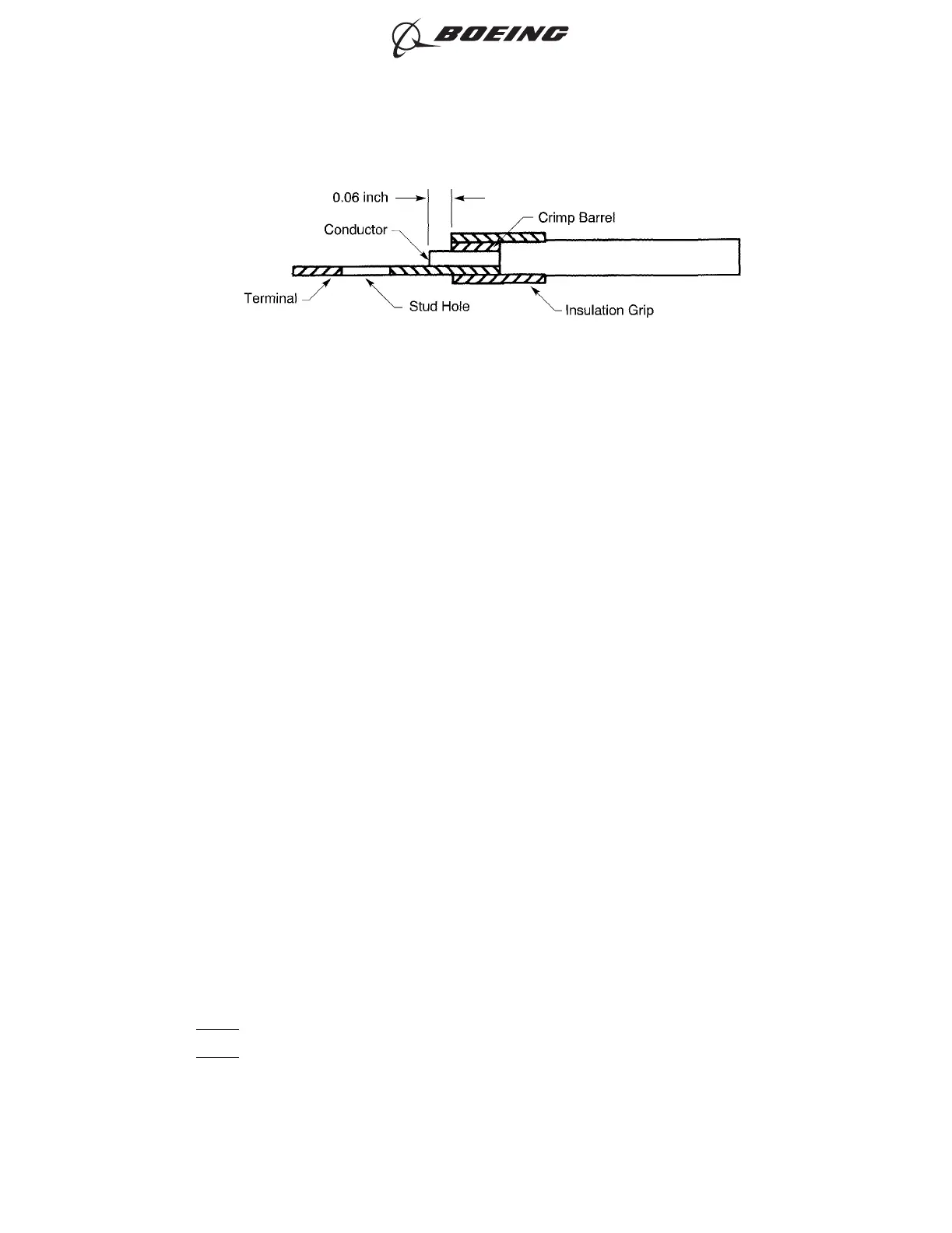
(6) Put the conductor of the wire in the crimp barrel of the terminal lug.
Make sure that:
• All of the strands of the conductor are in the crimp barrel
• The end of the conductor extends 0.06 ± 0.03 inch farther than the end of the crimp barrel
• If the terminal lug has an insulation grip, the end of the wire insulation is in the insulation
grip of the terminal lug
• If the terminal lug does not have an insulation grip, the maximum distance from the end of
the wire insulation of a single wire to the end of the crimp barrel is 0.12 inch for AWG 10 and
smaller, and 0.25 inch for AWG 8 and larger
• The clearance from the end of the conductor is sufficent for the installation of the washer
and the nut.
(7) Crimp the terminal lug.
Make sure that:
• All of the strands of the conductor are in the crimp barrel
• The end of the conductor extends 0.06 ± 0.03 inch farther than the end of the crimp barrel
• If the terminal lug has an insulation grip, the end of the wire insulation is in the insulation
grip of the terminal lug
• If the terminal lug has an insulation grip, the crimp tool is adjusted to give the correct
insulation support. Refer to Paragraph 2.B.
• If the terminal lug does not have an insulation grip, the maximum distance from the end of
the wire insulation of a single wire to the end of the crimp barrel is 0.12 inch for AWG 10 and
smaller, and 0.25 inch for AWG 8 and larger
• The clearance from the end of the conductor is sufficent for the installation of the washer
and the nut.
(8) If the crimp tool is a hex type tool from Table 69, crimp the terminal lug again with the secondary
die.
NOTE: The second crimp removes the flash that is made by the first crimp.
NOTE: The removal of the plating from the terminal lug caused by the second crimp is permitted.
(a) Put the secondary die in the crimp tool.
INSULATION REMOVAL LENGTH
Figure 28
ASSEMBLY OF INSULATED AND UNINSULATED TERMINAL LUGS
707, 727-787
STANDARD WIRING PRACTICES MANUAL
20-30-11
Page 104
Oct 15/2017D6-54446
ECCN 9E991 BOEING PROPRIETARY - See title page for details