• Starts 0.50 inch ±0.25 inch farther than the rear end of the inner ferrule at one end of the
splice
• Stops 0.50 inch ±0.25 inch farther than the rear end of the inner ferrule at the other end of
the splice
• Makes a 50 percent overlap.
(17) Tightly wind a second layer of the tape on the splice assembly.
Make sure that the layer of tape:
• Starts where the first layer of tape stops
• Stops where the first layer of tape starts
• Makes a 50 percent overlap.
(18) Align the center of the sleeve with the center of the splice assembly.
(19) Shrink the sleeve into position. Refer to Subject 20-10-14.
12. SEALED SPLICE CONFIGURATIONS WITH SHIELD-KONS FOR SHIELDED WIRE AND SHIELDED
CABLE
A. Splice Assembly Configurations
For the conditions that are applicable for:
• The repair of a wire or a cable with a splice, refer to Subject 20-10-13
• The selection of the correct sealed splice configuration, refer to Paragraph 1.C.
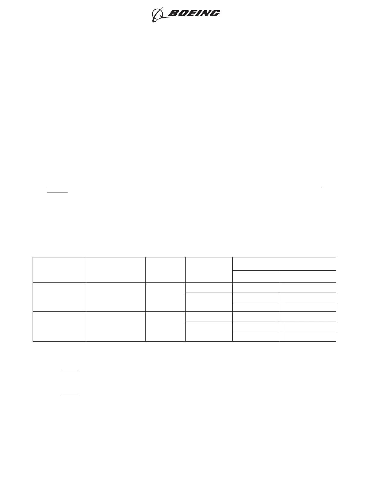
Table 103
SPLICE ASSEMBLY CONFIGURATIONS
One End of Splice
Assembly
Other End of Splice
Assembly
Quantity of
Conductor
Splices
Applicable
Condition
Splice Assembly
Configuration Procedure
One Shielded Wire One Shielded Wire 1
Fuel Vapor Tape, Ties Paragraph 12.B.
No Fuel Vapor
Tape, Sleeves Paragraph 12.C.
Tape, Ties Paragraph 12.B.
One Shielded Cable One Shielded Cable -
Fuel Vapor Tape, Ties Paragraph 12.D.
No Fuel Vapor
Tape, Sleeves Paragraph 12.E.
Tape, Ties Paragraph 12.D.
B. Sealed Splice Configurations for Shielded Wire and Cable - One Shielded Wire to One Shielded
Wire - Shield Kons, Tape, Ties
NOTE: The larger diameter Shield-Kons are no longer manufactured. For an alternative procedure to
assemble a splice for larger diameter shielded wire, refer to Paragraph 13.B. for the assembly
of a sealed splice with shield termination rings, shield terminator bands, tape and ties.
NOTE: If the correct diameter Shield-Kons are available, this procedure can be used:
For the conditions that are applicable for:
• The repair of a wire or a cable with a splice, refer to Subject 20-10-13
• The selection of the correct sealed splice configuration, refer to Paragraph 1.C.
ASSEMBLY OF SPLICES
707, 727-787
STANDARD WIRING PRACTICES MANUAL
20-30-12
Page 232
Jun 15/2021D6-54446
ECCN 9E991 BOEING PROPRIETARY - See title page for details