(1) If the splice kit and the wiring configuration at each end of the conductor splice are specified in
Table 4, do the special cable preparation. Refer to Paragraph 2.C..
(2) If the splice kit and the wiring configuration at each end of the conductor splice are not specified
in Table 4, do the standard cable preparation. Refer to Paragraph 2.B..
B. Cable Preparation - Standard Configuration
For the conditions that are applicable for this procedure, refer to Paragraph 2.A..
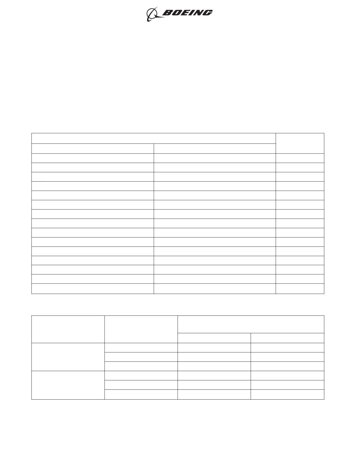
Table 5
CABLE PREPARATION
Wiring Configuration
Reference
One End of Conductor Splice Other End of Conductor Splice
1 Cable, 1 Conductor 1 Cable, 1 Conductor Figure 3
1 Cable, 1 Conductor 2 Cables, 1 Conductor each Figure 4
1 Cable, 1 Conductor 3 Cables, 1 Conductor each Figure 5
1 Cable, 2 Conductors 1 Cable, 2 Conductors Figure 6
1 Cable, 2 Conductors 2 Cables, 1 Conductor Figure 7
1 Cable, 2 Conductors 2 Cables, 2 Conductors each Figure 8
1 Cable, 2 Conductors 1 Cable, 2 Conductors 1 Cable, 1 Conductor Figure 9
1 Cable, 2 Conductors 1 Cable, 1 Conductor 1 Cable, 2 Conductors 1 Cable, 1 Conductor Figure 10
1 Cable, 2 Conductors 2 Cables, 1 Conductor each 2 Cables, 1 Conductor each Figure 11
1 Cable, 3 Conductors 1 Cable, 3 Conductors Figure 6
1 Cable, 3 Conductors 2 Cables, 3 Conductors each Figure 12
1 Cable, 4 Conductors 1 Cable, 4 Conductors Figure 6
1 Cable, 4 Conductors 1 Cable, 4 Conductors 1 Cable, 1 Conductor Figure 13
2 Cables, 1 Conductor each 2 Cables, 1 Conductor each Figure 14
2 Cables, 2 Conductors each 2 Cables, 2 Conductors each Figure 15
Table 6
CABLE PREPARATION DIMENSIONS
Splice Kit Part Number Dimension
Length
(inch)
Target Tolerance
BACS52R1T1
A 1.00 ±0.02
B 0.38 ±0.02
C 0.28 ±0.02
BACS52R1T2
A 2.10 ±0.02
B 0.38 ±0.02
C 0.28 ±0.02
ASSEMBLY OF BACS52R SHIELDED SPLICES
707, 727-787
STANDARD WIRING PRACTICES MANUAL
20-30-19
Page 6
Oct 15/2015D6-54446
ECCN 9E991 BOEING PROPRIETARY - See title page for details