• Stops 0.50 inch ±0.25 inch farther than the rear end of the solder sleeve at the other end of
the splice
• Makes a 50 percent overlap.
(18) Tightly wind a second layer of the tape on the splice assembly.
Make sure that the layer of tape:
• Starts 1 inch minimum farther than where the first layer of tape stops
• Stops 1 inch minimum farther than where the first layer of tape starts
• Makes a 50 percent overlap.
(19) Align the center of the heat shrinkable sleeve with the center of the splice assembly.
(20) Shrink the sleeve into its position. Refer to Subject 20-10-14.
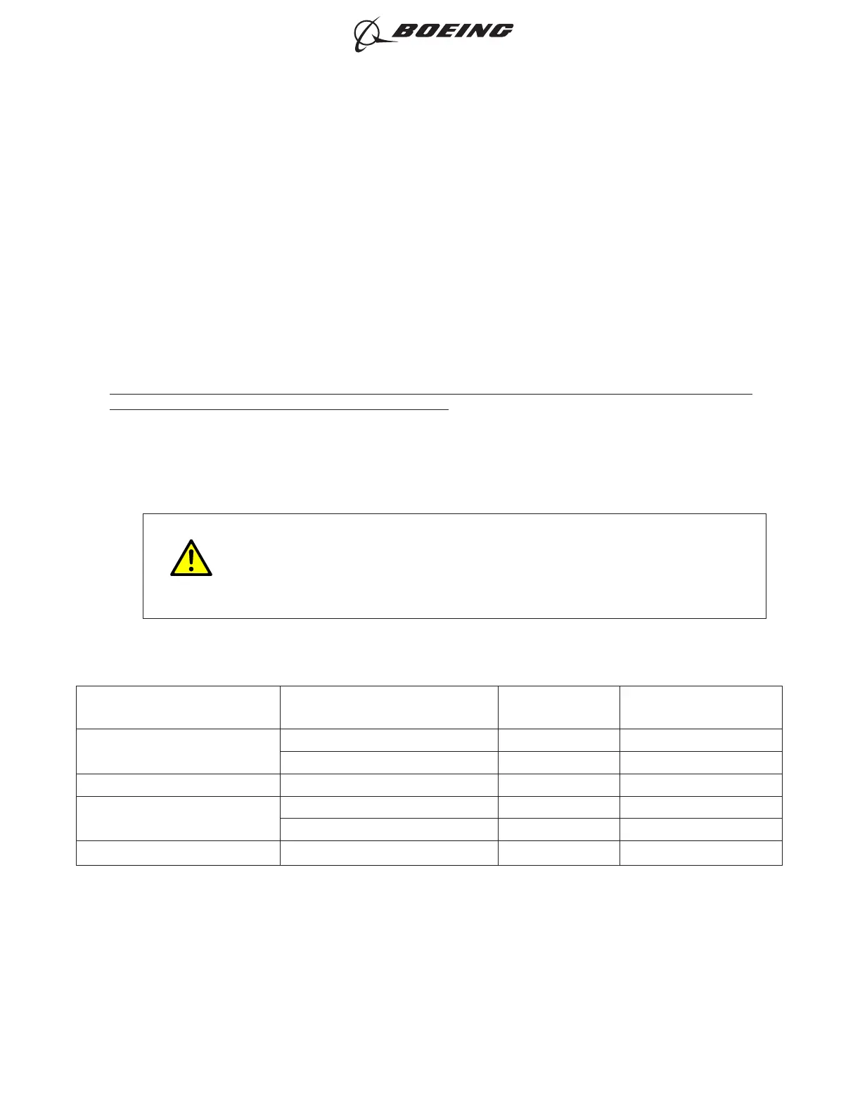
16. SEALED SPLICE CONFIGURATIONS WITH SOLDER SLEEVE SPLICE KITS FOR SHIELDED WIRE
AND SHIELDED CABLE FOR HIGH TEMPERATURE
A. Splice Assembly Configurations
For the conditions that are applicable for:
• The repair of a wire or a cable with a splice, refer to Subject 20-10-13
• The selection of the correct sealed splice configuration, refer to Paragraph 1.C.
CAUTION
THESE SPLICE ASSEMBLY CONFIGURATIONS CONTAIN SOLDER SLEEVES
THAT ARE APPLICABLE FOR WIRE AND CABLE WITH NICKEL PLATED
SHIELDS. ASSEMBLY OF THE SPLICE ON WIRE AND CABLE WITHOUT
NICKEL PLATED SHIELDS CAN CAUSE UNSATISFACTORY PERFORMACE
AND RELIABILITY OF THE SPLICE. REFER TO SUBJECT 20-00-13 FOR THE
CONFIGURATION OF THE WIRE OR CABLE.
Table 141
WIRE AND CABLE CONFIGURATIONS
One End of Splice Assembly Other End of Splice Assembly
Quantity of
Conductor Splices
Splice Kit Part Number
One Shielded Wire
One Shielded Wire 1 D-150-0250
Two Shielded Wires 1 D-150-0251
Two Shielded Wires One Shielded Wire 1 D-150-0251
One Class 2 Shielded Cable
One Class 2 Shielded Cable 2 D-150-0252
Two Class 2 Shielded Cables 2 D-150-0253
Two Class 2 Shielded Cables One Class 2 Shielded Cable 2 D-150-0253
ASSEMBLY OF SPLICES
707, 727-787
STANDARD WIRING PRACTICES MANUAL
20-30-12
Page 335
Jun 15/2021D6-54446
ECCN 9E991 BOEING PROPRIETARY - See title page for details