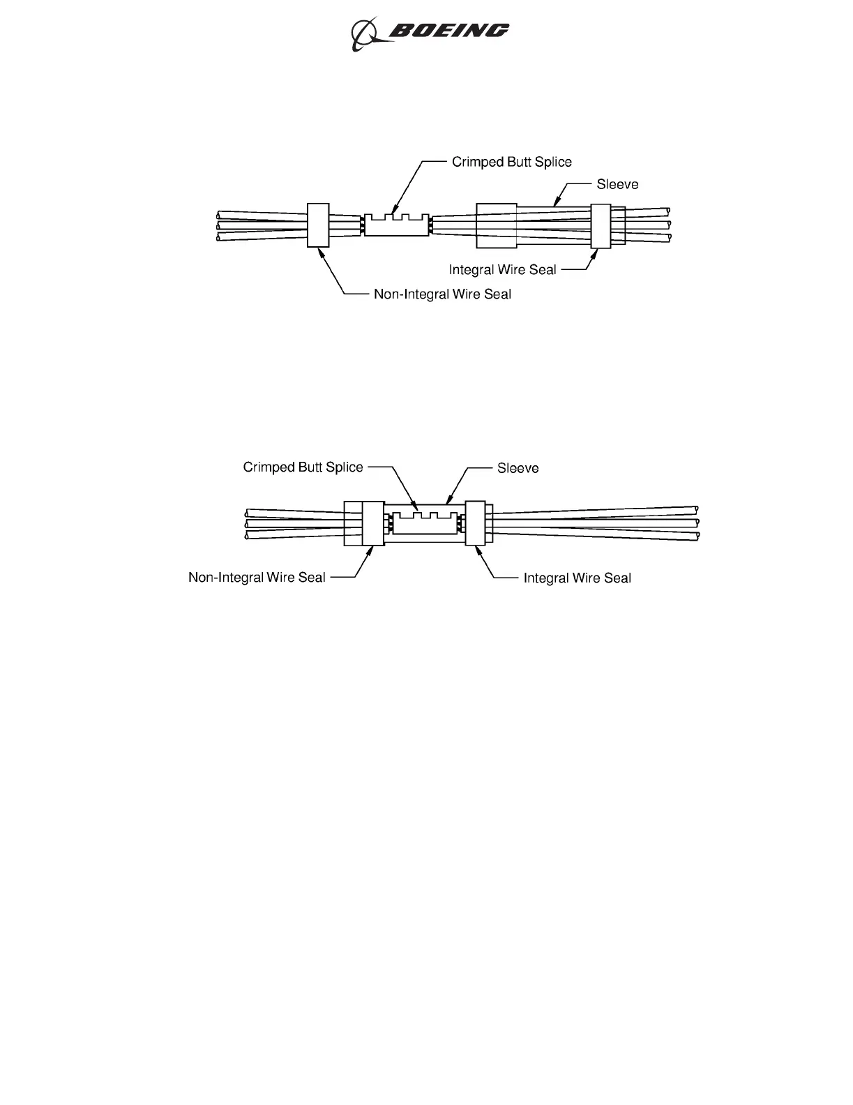
(10) Align the center of the sleeve with the center of the butt splice.
(11) Push the non-integral wire seal fully into the sleeve until it is as near the splice as possible. Refer
to Figure 79.
(12) Shrink the sleeve into position. Refer to Subject 20-10-14.
Make sure that the seal material that comes out of the ends of the sleeve does not have rough
edges.
J. Sealed Splice Configurations for Unshielded Wires and Cables - One to Five Wires to One to
Five Wires - Sleeve
For the conditions that are applicable for:
• The repair of a wire or a cable with a splice, refer to Subject 20-10-13
• The selection of the correct sealed splice configuration, refer to Paragraph 1.C.
(1) Make a selection of a butt splice from Table 12 or Table 14.
Make sure that the splice has the smallest CAU range that can accept the total CAU of the
conductor.
Refer to Paragraph 1.D. for the procedure to calculate the CAU of the conductor.
(2) Find the crimp barrel size of the splice from Table 12 or Table 14.
(3) Make a selection of a crimp tool from:
CRIMPED SPLICE ASSEMBLY
Figure 78
POSITION OF THE SLEEVE AND THE WIRE SEAL
Figure 79
ASSEMBLY OF SPLICES
707, 727-787
STANDARD WIRING PRACTICES MANUAL
20-30-12
Page 108
Feb 15/2021D6-54446
ECCN 9E991 BOEING PROPRIETARY - See title page for details