(18) If the crimp area has flash that is caused by the crimp operation:
Table 18
NECESSARY TOOLS
Tool Type Supplier
File Fine Tooth An available source
(a) Make a selection of a file from Table 18.
(b) Remove the flash with file.
Make sure that the width of the filed area is not more than 0.125 inch.
NOTE: Exposed base material where flash is removed is an normal condition.
(c) Remove the filings from the assembly.
(19) If the crimp area has flaked plating that is caused by the crimp operation, remove the flaked
plating.
NOTE: Exposed base material where flaked plating is removed is an normal condition.
I. Insulation of the Splice - AMP 277156-1 and AMP 277157-1 Splices with AWG 10 Wire
(1) Make a selection of a solvent from Table 7.
(2) With a clean wiper and solvent, clean the splice and a minimum of two inches of the wire from
each end of the splice.
(3) Dry the cleaned area with a clean wiper.
(4) If heat shrinkable sleeves are used for splice insulation, install the sleeves.
(a) On one of the wires, push the 1/4 inch diameter sleeve to the splice until the forward end of
the sleeve is against the end of the splice. Refer to Figure 15.
Make sure that:
• The end of the sleeve is a maximum of 0.1 inch from the end of the splice
• The sleeve does not make an overlap with the splice.
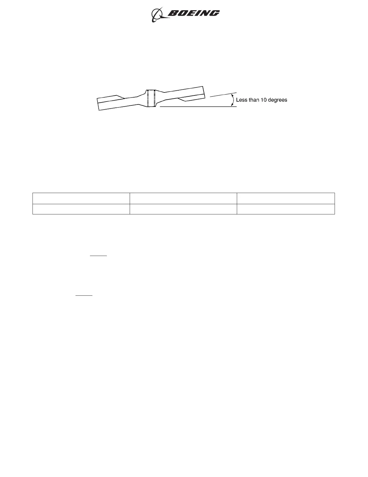
CONFIGURATION OF THE SPLICE
Figure 14
ASSEMBLY AND REPAIR OF THE AMP AND BACS52N COPALUM SPLICES
707, 727-787
STANDARD WIRING PRACTICES MANUAL
20-30-13
Page 27
Oct 15/2015D6-54446
ECCN 9E991 BOEING PROPRIETARY - See title page for details