C. Insulation of AWG 8 or Larger Terminals
Table 3
HEAT SHRINKABLE SLEEVES FOR SINGLE PHASE AND DC WIRES
Area Temperature Range
(degrees F)
Heat Shrinkable Sleeve
Part Number or Description Supplier
Less than or equal to 275 Grade B, Class 1 Heat Shrinkable Sleeve Refer to Subject 20-00-11.
Greater than 275
Thermofit TFE Raychem (Tyco)
Thermofit TFE-R Raychem (Tyco)
Ben-Har 1151-FRB Bentley-Harris (Federal-Mogul)
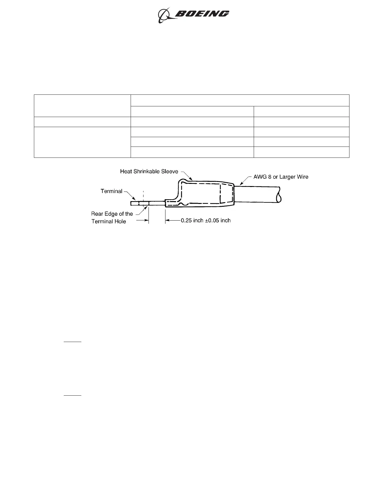
It is necessary to install a heat shrinkable sleeve on AWG 8 and larger wires that have a terminal
attached. The sleeve:
• Must not be in between the different components of the terminal hardware
• Can extend over the pressure washer, but must not touch the terminal stud
• Must be yellow for single phase and DC wires; refer to Table 3
• Must be installed on the terminal after the terminal is attached to the wire
• Must have the smallest possible diameter that can be installed over the wire barrel of the terminal
• Must be 1-1/2 inches to 2 inches in length.
NOTE: When two wires from a single terminal start to go in different directions within 1/2 inch of the
terminal, the permitted length of the sleeve is 1 inch minimum.
When a Thermofit TFE heat shrinkable sleeve is used:
• The phase identification sleeve is installed over the Thermofit TFE sleeve
• The sleeve is held in position with a wire bundle tie on the wire barrel of the terminal or on the
wire beyond the terminal.
NOTE: In fuel vapor areas, the sleeve can be held in position with a wire bundle tie.
When the terminal is attached to the equipment, these conditions are applicable:
• If it is necessary, the sleeve can be cut so that it is clear of the hardware
• If there is a barrier between phases or components, the sleeves of adjacent terminals must not
touch each other.
INSULATION OF AWG 8 AND LARGER WIRE WITH A TERMINAL
Figure 2
ELECTRICAL CONNECTION OF EQUIPMENT AND INSTALLATION OF TERMINAL LUGS
707, 727-787
STANDARD WIRING PRACTICES MANUAL
20-30-00
Page 5
Oct 15/2015D6-54446
ECCN 9E991 BOEING PROPRIETARY - See title page for details