F. Sealed Splice Configurations for Unshielded Wires and Cables for High Temperature - Two
Wires to Two Wires - Tape, Ties
For the conditions that are applicable for:
• The repair of a wire or a cable with a splice, refer to Subject 20-10-13
• The selection of the correct sealed splice configuration, refer to Paragraph 1.C.
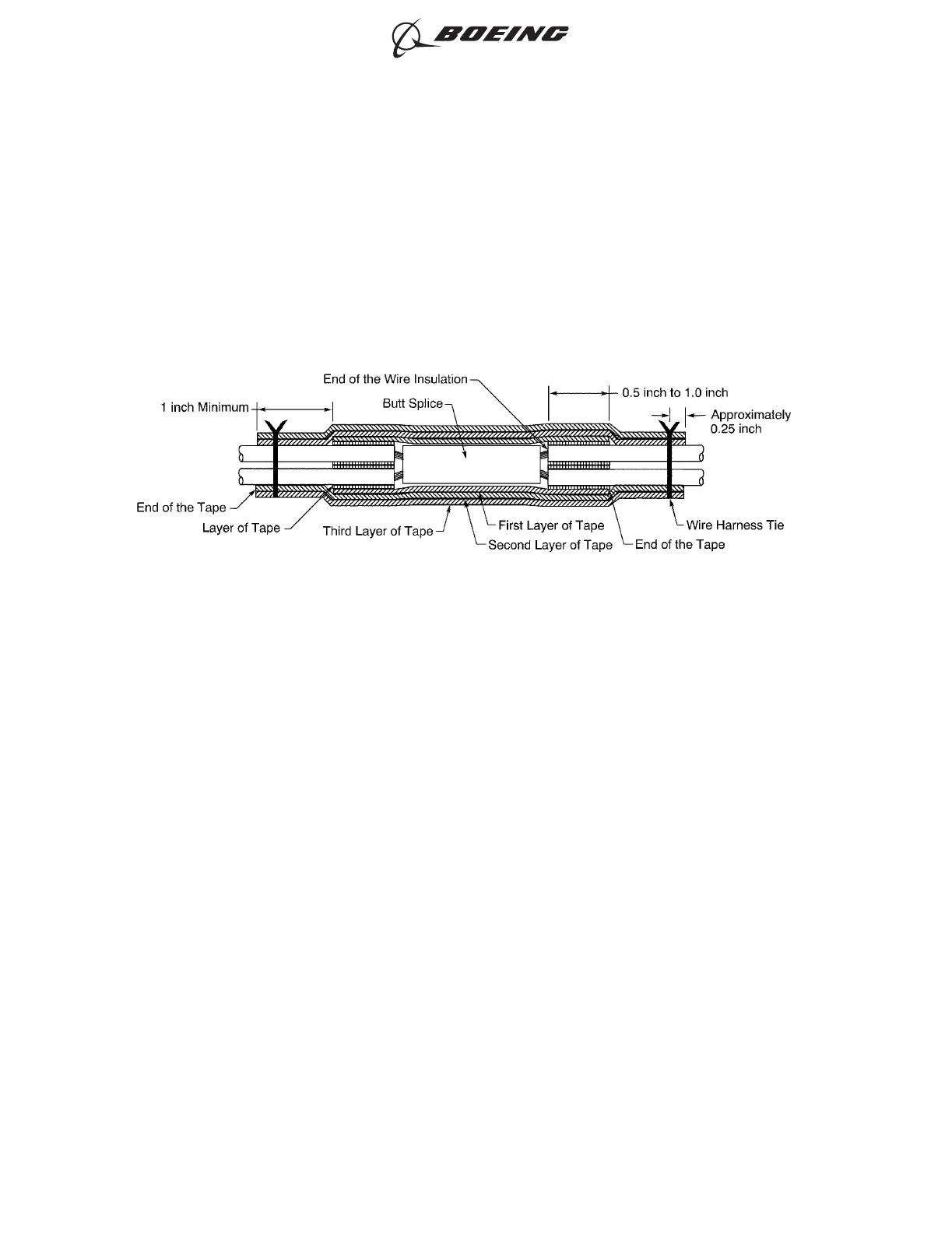
Refer to Figure 111.
(1) Make a selection of a butt splice from Table 15.
Make sure that the splice has the smallest CAU range that can accept the total CAU of the
conductors.
Refer to Paragraph 1.D. for the procedure to calculate the CAU of the conductor.
(2) Find the crimp barrel size of the splice from Table 15.
(3) Make a selection of a crimp tool from Table 46.
(4) Make a selection of a Temperature Grade D insulation tape from Table 52.
Make sure that the tape has a width of 0.5 inch minimum to 1.0 inch maximum.
(5) Remove the necessary length of insulation from the end of each wire.
Refer to:
• Figure 112
• Table 89 for the insulation removal length
• Subject 20-00-15 for the insulation removal procedures.
CONFIGURATION OF THE SPLICE ASSEMBLY
Figure 111
ASSEMBLY OF SPLICES
707, 727-787
STANDARD WIRING PRACTICES MANUAL
20-30-12
Page 138
Jun 15/2021D6-54446
ECCN 9E991 BOEING PROPRIETARY - See title page for details