(a) Push the sleeve forward until the forward end of the sleeve is aligned with the rear end of
the tongue of the terminal lug.
(b) Shrink the sleeve into its position. Refer to Subject 20-10-14.
Make sure that the sleeve has a tight fit on the assembly.
J. Extension of the Terminal Lug Assembly Insulation - Standard Configuration
This procedure is applicable when one of these conditions occur:
• The 0.5 inch Type I 20 mil silicone tape is specified for a BACT13K-2, BACT13K-3, or
BACT13K-4 terminal lug
• The 0.5 inch Type I 20 mil silicone tape and the standard extension of the insulation of the
terminal lug assembly are specified for the terminal lug.
Table 24
ASSEMBLY COMPONENTS
Component Type Part Number
Tape Silicone, Type I, 20 mil A-A-59163-1I0020-0.500
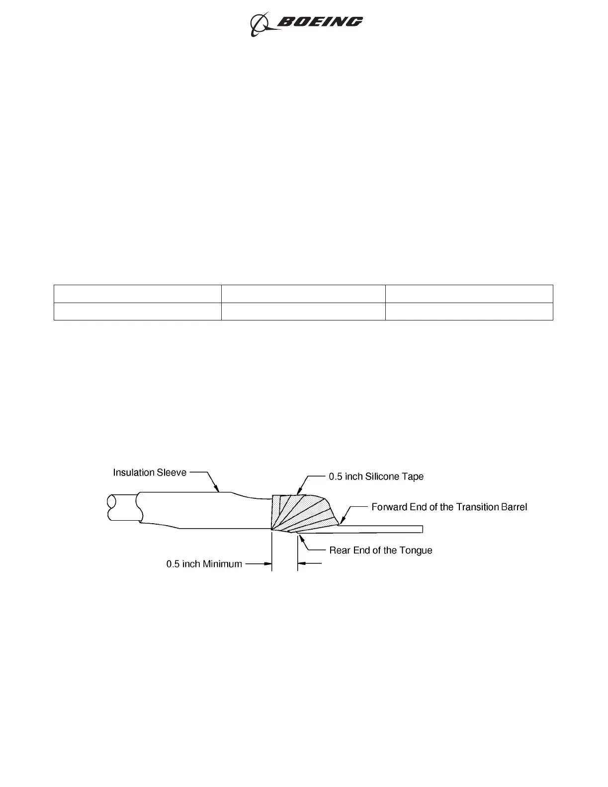
(1) Put two layers of the specified tape on the transition barrel of the terminal lug. Refer to Figure 26,
Make sure that:
• The forward end of each layer is aligned with the forward end of the transition barrel
• The rear end of each layer extends 0.5 inch minimum rearward from the rear end of the
tongue of the terminal lug
• Each layer makes a 50 percent overlap with itself
• The second layer of tape is wound in the opposite direction of the first layer
• The layers of tape do not make an overlap with the bottom surface of the tongue of the
terminal lug.
(2) Examine the extension of the terminal lug insulation.
Make sure that the tape does not make an overlap with the rear end of the bottom of the tongue
of the terminal lug.
POSITION OF THE TAPE ON THE TRANSITION BARREL
Figure 26
ASSEMBLY OF AMP (TYCO) COPALUM, MS25435 AND THOMAS & BETTS ALUMINUM
TERMINALS
707, 727-787
STANDARD WIRING PRACTICES MANUAL
20-30-14
Page 35
Oct 15/2015D6-54446
ECCN 9E991 BOEING PROPRIETARY - See title page for details