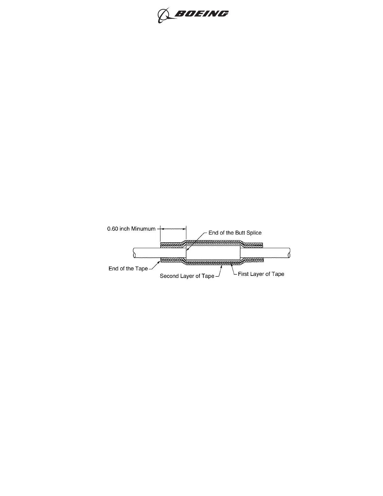
• Starts at the rear end of the layers of tape on the two wires on one end of the splice
assembly
• Stops at the rear end of the layers of tape on the two wires on the other end of the
splice assembly
• Makes a 50 percent overlap.
(b) Tightly wind the second layer of tape on the splice assembly in the opposite direction of the
first layer.
Make sure that the layer:
• Starts where the first layer stops
• Stops where the first layer starts
• Makes a 50 percent overlap.
E. Internal Conductor Splice for a Shielded Wire or Cable - One Wire to One Wire for High
Temperature - Tape
For the conditions that are applicable for:
• The repair of a wire or a cable with a splice, refer to Subject 20-10-13
• The selection of the correct sealed splice configuration, refer to Paragraph 1.C.
Refer to Figure 133.
(1) Find the CAU of the conductor.
Refer to Paragraph 1.D. for the procedure to calculate the CAU of the conductor.
(2) If the CAU of the conductor is less than the minimim CAU for the butt splice, increase the CAU of
the conductor.
Refer to:
• Table 15 for the minimum CAU of the butt splice
• Paragraph 2. for the applicable conditions and procedures for the increase of the CAU.
(3) Make a selection of a butt splice from Table 15.
Make sure that the splice has the smallest CAU range that can accept the total CAU of the
conductor.
(4) Find the crimp barrel size of the splice from Table 15.
CONFIGURATION OF THE SPLICE ASSEMBLY
Figure 133
ASSEMBLY OF SPLICES
707, 727-787
STANDARD WIRING PRACTICES MANUAL
20-30-12
Page 159
Jun 15/2021D6-54446
ECCN 9E991 BOEING PROPRIETARY - See title page for details