(11) Crimp the splice.
(12) Align the center of the sleeve with the center of the splice.
(13) Shrink the sleeve into position. Refer to Figure 11 and Subject 20-10-14.
C. Closed End Splice Configurations - Sealed Closed End Splice - Parallel Splice, Sleeve
(1) Make a selection of a parallel splice from Table 8.
Make sure that the splice has the smallest CAU range that can accept the total CAU of the
conductors. Refer to Paragraph 1.D. for the procedure to calculate the CAU of the conductors.
(2) Make a selection of a sleeve from Table 9.
Make sure the sleeve is for:
• The applicable parallel splice
• The maximum number of wires.
(3) Find the crimp barrel size of the splice from Table 8.
(4) Make a selection of a crimp tool from:
• Table 38 for AMP 3413() parallel splices
• Table 39 for Raychem D-609-0() parallel splices.
(5) For a sleeve with a 5 hole wire seal, put the sleeve on the wires. Refer to Figure 2.
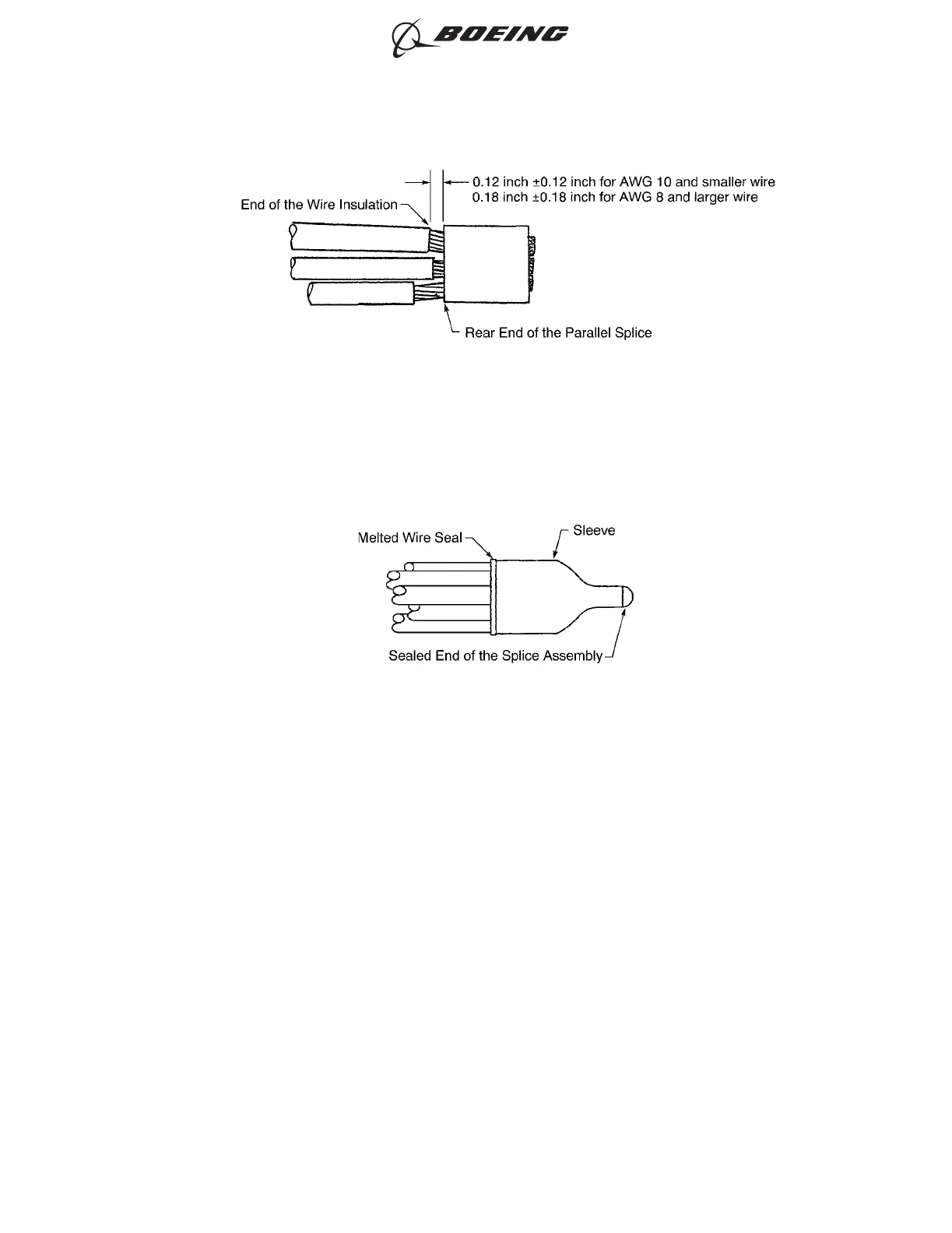
POSITION OF EACH WIRE IN THE PARALLEL SPLICE
Figure 10
CONFIGURATION OF THE SPLICE ASSEMBLY
Figure 11
ASSEMBLY OF SPLICES
707, 727-787
STANDARD WIRING PRACTICES MANUAL
20-30-12
Page 57
Feb 15/2021D6-54446
ECCN 9E991 BOEING PROPRIETARY - See title page for details