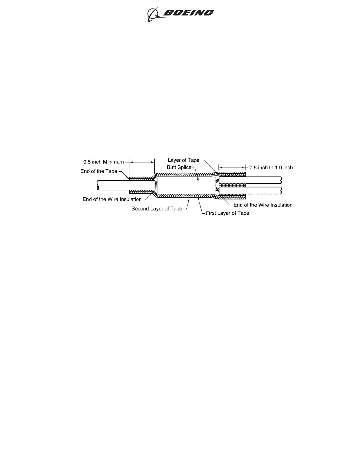
• Stops 0.5 inch minimum farther than the end of the wire insulation at the other end of
the splice assembly
• Makes a 50 percent overlap.
(b) Tightly wind the second layer of tape on the splice assembly in the opposite direction of the
first layer.
Make sure that the layer:
• Starts where the first layer stops
• Stops where the first layer starts
• Makes a minimum 50 percent overlap.
C. Internal Conductor Splice for a Shielded Wire or Cable - One Wire to Two Wires - Tape
Refer to Figure 125.
(1) Make a selection of a butt splice from Table 12 or Table 14.
Make sure that the splice has the smallest CAU range that can accept the total CAU of the
conductor.
Refer to Paragraph 1.D. for the procedure to calculate the CAU of the conductor.
(2) Find the crimp barrel size of the splice from Table 12 or Table 14.
(3) Make a selection of a crimp tool from:
• Table 43 for BACT12C() splices
• Table 44 for NAS1387-() splices
• Table 45 for BACS52K() splices
• Table 45 for Raychem D-609-0() splices.
(4) Make a selection of a Temperature Grade B or higher insulation tape from Table 52.
Make sure that the tape has a width of 0.5 inch minimum to 1.0 inch maximum.
(5) Remove the necessary length of insulation from the end of each wire.
Refer to:
• Figure 126
• Table 93 for the insulation removal length
CONFIGURATION OF THE SPLICE ASSEMBLY
Figure 125
ASSEMBLY OF SPLICES
707, 727-787
STANDARD WIRING PRACTICES MANUAL
20-30-12
Page 152
Jun 15/2021D6-54446
ECCN 9E991 BOEING PROPRIETARY - See title page for details