C. Assembly of the Splice Connector
For the applicable conditions for the assembly of a splice, refer to Paragraph 1.A.
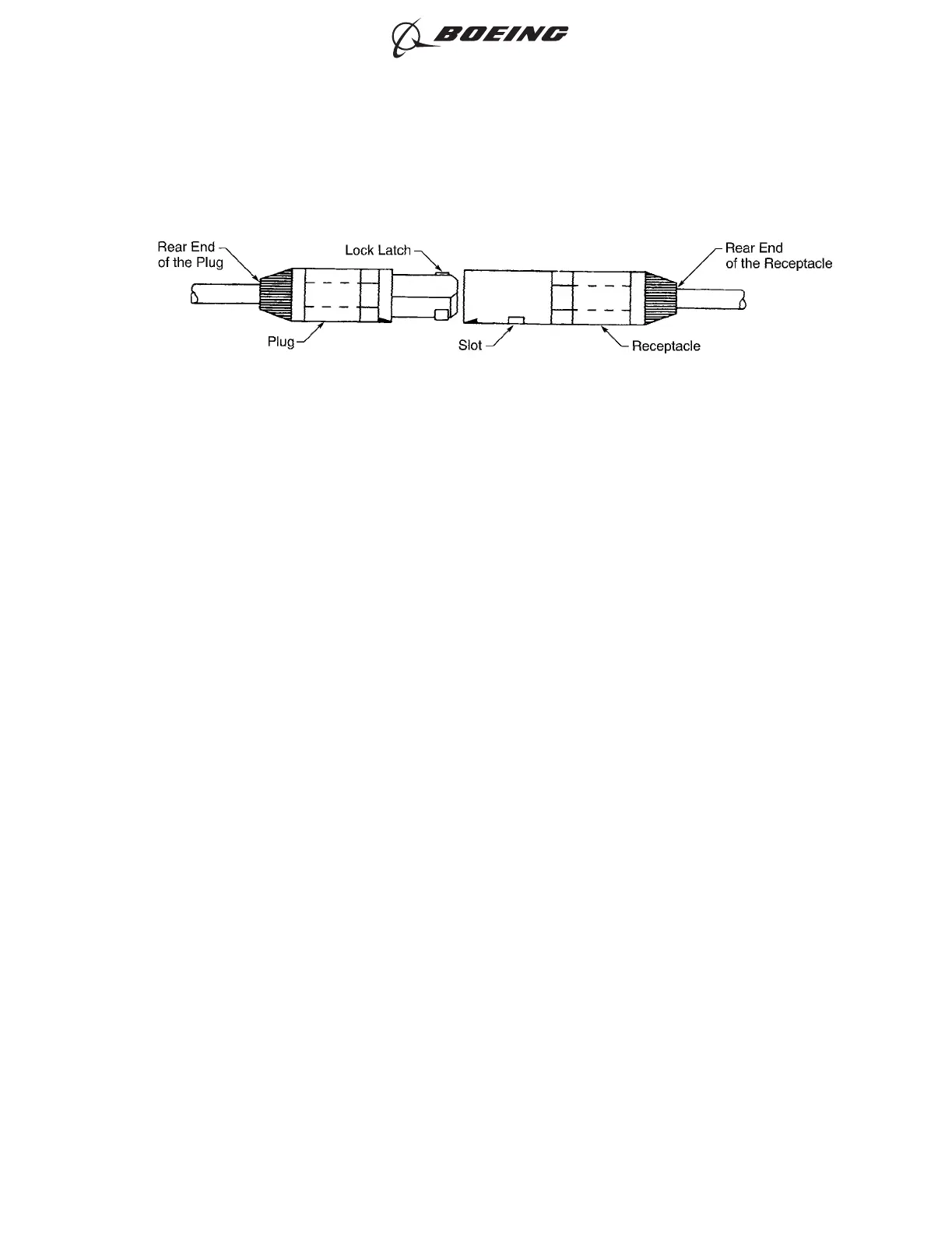
Refer to Figure 307.
(1) Make a selection of a splice plug from Table 27.
(2) Make a selection of a splice receptacle from Table 28.
(3) Make a selection of the contacts for the plug and receptacle from Table 29.
(4) Make a selection of a contact crimp tool. Refer to Subject 20-61-11.
(5) Make a selection of a size 16 contact insertion tool. Refer to Subject 20-61-11.
(6) Remove 0.28 inch ±0.03 inch of insulation from the each end of the wire.
(7) Assemble the receptacle side of the splice:
(a) Put the wire in the crimp barrel of the socket contact.
Make sure that:
• All of the strands of the conductor are in the crimp barrel
• The conductor can be seen in the inspection hole
• The distance from the end of the insulation to the end of the crimp barrel is not more
than 0.03 inch.
(b) Crimp the contact.
(c) At the rear of the receptacle, axially align the contact and the tool with the contact cavity.
(d) Push the tool into the contact cavity unil it stops.
(e) Remove the tool from the contact cavity.
(f) Lightly pull the wire to make sure that the contact is locked in its position.
SPLICE ASSEMBLY
Figure 307
ASSEMBLY OF SPLICES
707, 727-787
STANDARD WIRING PRACTICES MANUAL
20-30-12
Page 351
Jun 15/2021D6-54446
ECCN 9E991 BOEING PROPRIETARY - See title page for details