• The outer sleeve
• A solder sleeve
• The shield material.
Make sure that the small end of the solder sleeve is put on the cable first.
(6) Put Wires A1 and B1 together
(7) Put a seal sleeve on the Wire A1 and Wire B1 pair.
(8) Put a seal sleeve on the Wire D1.
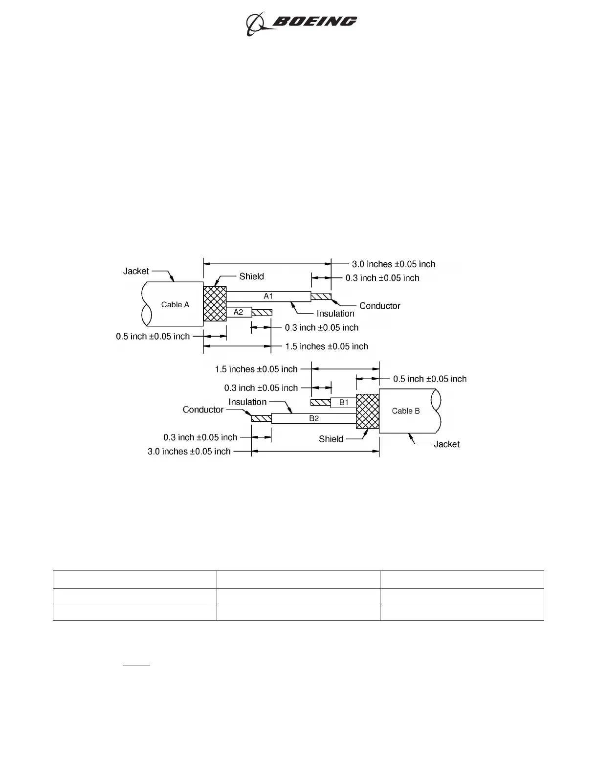
G. Kit Groups P1N2, P2N2 or P3N2 - One Class 2 Cable to One Class 2 Cable
Refer to Figure 13.
Table 15
CONNECTIONS
Wire Connection Wire Connected to
A1 Splice B1
A2 Splice B2
(1) Remove approximately 0.05 inch from each end of the shield material with a pair of scissors or an
equivalent tool.
NOTE: The shield material has fused ends that hold the ends of the strands of the shield
together.
ONE CLASS 2 CABLE TO ONE CLASS 2 CABLE
Figure 13
ASSEMBLY OF BACS52P SERIES AND D-150-0300 SERIES SHIELDED SPLICE ASSEMBLIES
707, 727-787
STANDARD WIRING PRACTICES MANUAL
20-30-20
Page 89
Jun 15/2021D6-54446
ECCN 9E991 BOEING PROPRIETARY - See title page for details