(5) Push the tool forward toward the end of the wire until the tool is against the rear end of the
terminal lug.
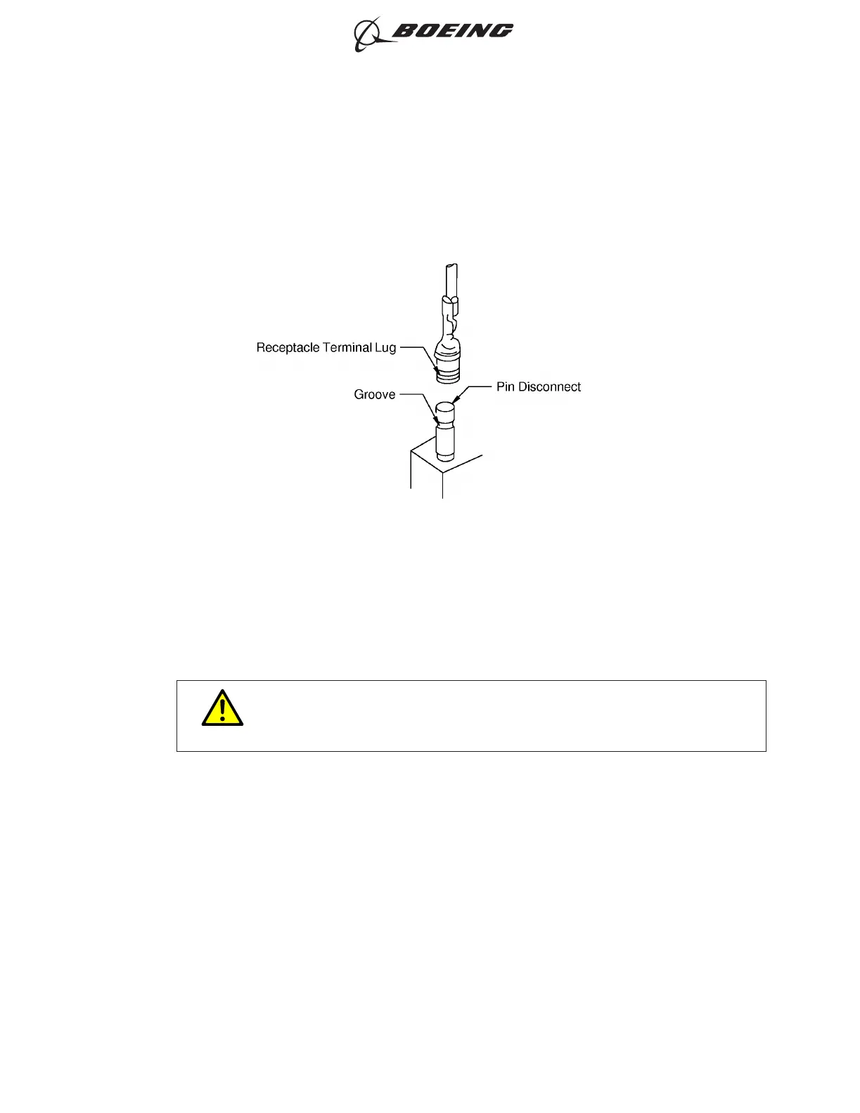
(6) Axially align the terminal lug and the pin disconnect. Refer to Figure 23.
(7) Push the terminal lug forward until the ring on the inside of the engaging end of the receptacle is
in the groove on the pin disconnect.
Make sure that the terminal lug and the pin disconnect stay aligned.
CAUTION
IF THE TERMINAL LUG AND THE PIN DISCONNECT DO NOT STAY
ALIGNED, DAMAGE TO THE LUG OR THE PIN CAN OCCUR.
G. Installation Torque for Circuit Breaker or Switch Collar Mounting Nut
For the installation of a circuit breaker or a switch that is installed with a 0.469-32 (15/32-32) or
0.625-24 (5/8-24) thread mount collar nut, torque the collar nut to 30 ±5 inch pounds unless otherwise
specified.
ALIGNMENT OF THE TERMINAL LUG AND THE PIN DISCONNECT
Figure 23
ELECTRICAL CONNECTION OF EQUIPMENT AND INSTALLATION OF TERMINAL LUGS
707, 727-787
STANDARD WIRING PRACTICES MANUAL
20-30-00
Page 25
Jun 15/2018D6-54446
ECCN 9E991 BOEING PROPRIETARY - See title page for details