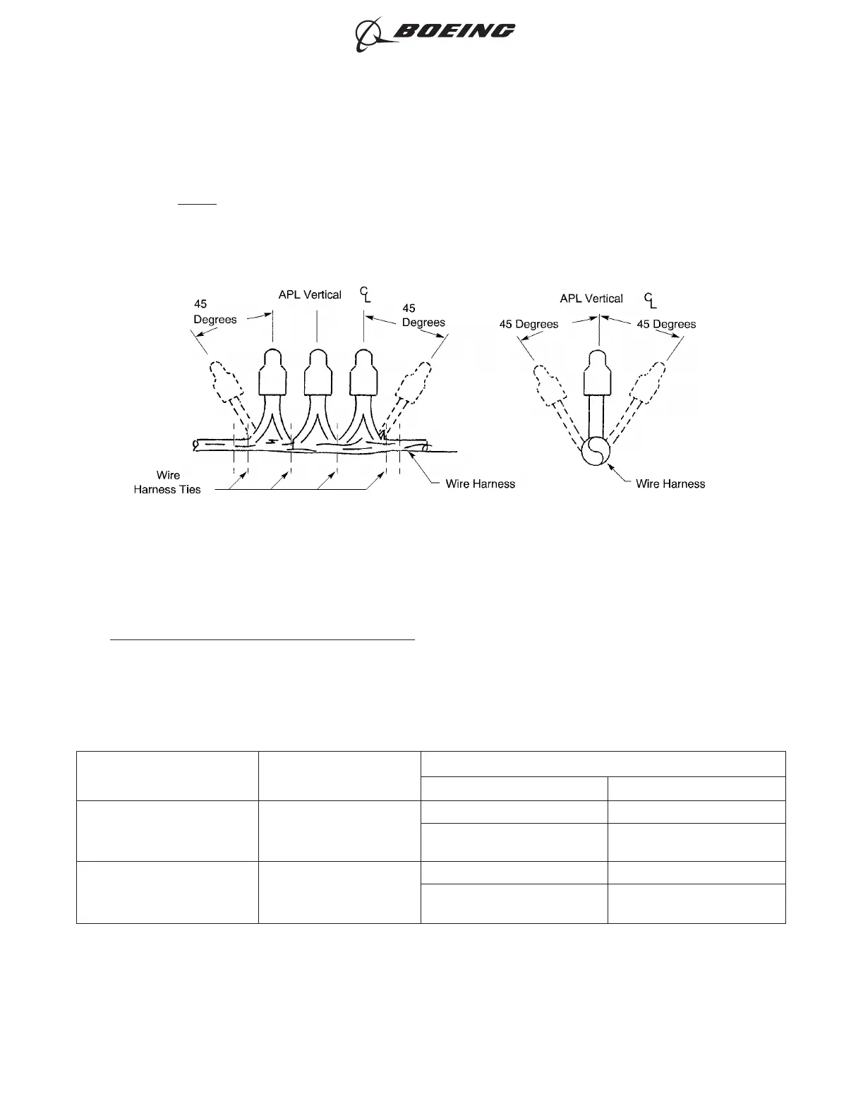
• Each splice is in the position that is ±45 degrees from the vertical.
Refer to Figure 23.
NOTE: This configuration is not necessary for splices that are in a module.
6. UNSEALED BUTT SPLICE CONFIGURATIONS
A. Splice Assembly Configurations
For the conditions that are applicable for an unsealed butt splice, refer to Paragraph 1.A.
Table 62
UNSEALED BUTT SPLICE CONFIGURATIONS
One End of Splice Assembly
Other End of Splice
Assembly
Splice Assembly
Configuration Procedure
One Wire One Wire
Insulated Butt Splice Paragraph 6.B.
Uninsulated Butt Splice with
Sleeve
Paragraph 6.D.
More Than One Wire More Than One Wire
Insulated Butt Splice Paragraph 6.C.
Uninsulated Butt Splice with
Sleeves
Paragraph 6.E.
CONFIGURATION OF THE CLOSED END SPLICES
Figure 23
ASSEMBLY OF SPLICES
707, 727-787
STANDARD WIRING PRACTICES MANUAL
20-30-12
Page 66
Feb 15/2021D6-54446
ECCN 9E991 BOEING PROPRIETARY - See title page for details