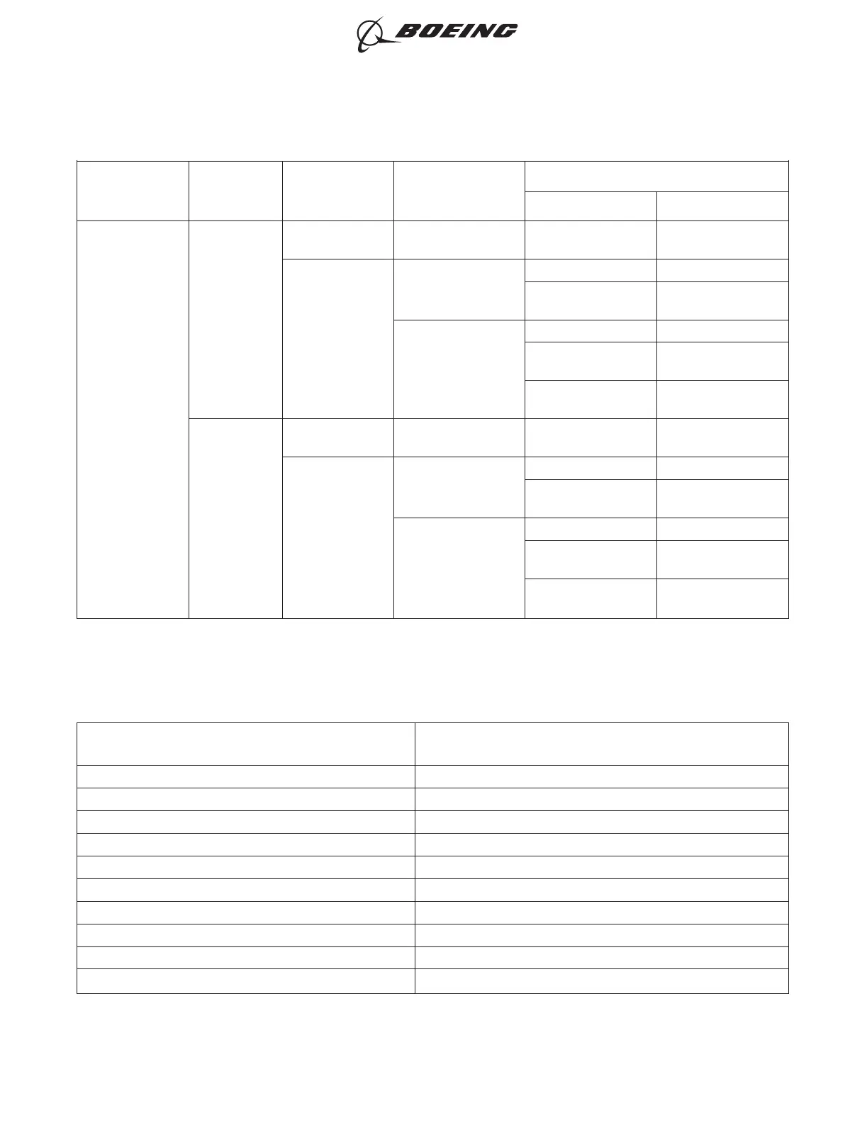
Table 3 SEALED SPLICE CONFIGURATIONS FOR SHIELDED WIRE AND SHIELDED CABLE (Continued)
Maximum
Temperature
Grade
Number of
Shields
Shield
Conductor
Applicable Area
Splice Assembly
Configuration Reference
D
1
Flat No Fuel Vapor
Solder Sleeve Splice
Kit
Paragraph 16.A.
Round
Fuel Vapor
Mechanical Ferrule Paragraph 11.A.
Shield Termination
Rings and Bands
Paragraph 13.A.
No Fuel Vapor
Mechanical Ferrule Paragraph 11.A.
Shield Termination
Rings and Bands
Paragraph 13.A.
Solder Sleeve Splice
Kit
Paragraph 16.A.
2
Flat Inner, Round
Outer
No Fuel Vapor
Solder Sleeve Splice
Kit
Paragraph 16.A.
Round Inner,
Round Outer
Fuel Vapor
Mechanical Ferrule Paragraph 11.A.
Shield Termination
Rings and Bands
Paragraph 13.A.
No Fuel Vapor
Mechanical Ferrule Paragraph 11.A.
Shield Termination
Rings and Bands
Paragraph 13.A.
Solder Sleeve Splice
Kit
Paragraph 16.A.
D. Conductor CAU
This paragraph gives the procedure to find the CAU of the conductor or conductors.
Table 4
AWG TO CAU CONVERSION
Wire Size
(AWG)
Circular Area Units
(CAU)
32 0.6
30 1
28 1.6
26 3
24 5
22 8
20 12
18 19
16 24
14 38
ASSEMBLY OF SPLICES
707, 727-787
STANDARD WIRING PRACTICES MANUAL
20-30-12
Page 11
Oct 15/2017D6-54446
ECCN 9E991 BOEING PROPRIETARY - See title page for details