14. SEALED SPLICE CONFIGURATIONS WITH SOLDER SHIELD SPLICE KITS FOR SHIELDED WIRE AND
SHIELDED CABLE
A. Splice Assembly Configurations
For the conditions that are applicable for:
• The repair of a wire or a cable with a splice, refer to Subject 20-10-13
• The selection of the correct sealed splice configuration, refer to Paragraph 1.C.
Table 105
SPLICE ASSEMBLY CONFIGURATIONS
One End of Splice Assembly Other End of Splice Assembly
Quantity of
Conductor
Splices
Paragraph
One Shielded Wire
One Shielded Wire 1 Paragraph 14.B.
One Shielded Wire and One Wire 1 Paragraph 14.D.
One Shielded Wire With an I-line Resistor
or Diode
One Shielded Wire 2 Paragraph 7.M
Three Shielded Wires
Three Shielded Wires 1 Paragraph 14.E.
One Class 3 Shielded Cable 3 Paragraph 14.L.
Four Shielded Wires Four Shielded Wires 1 Paragraph 14.F.
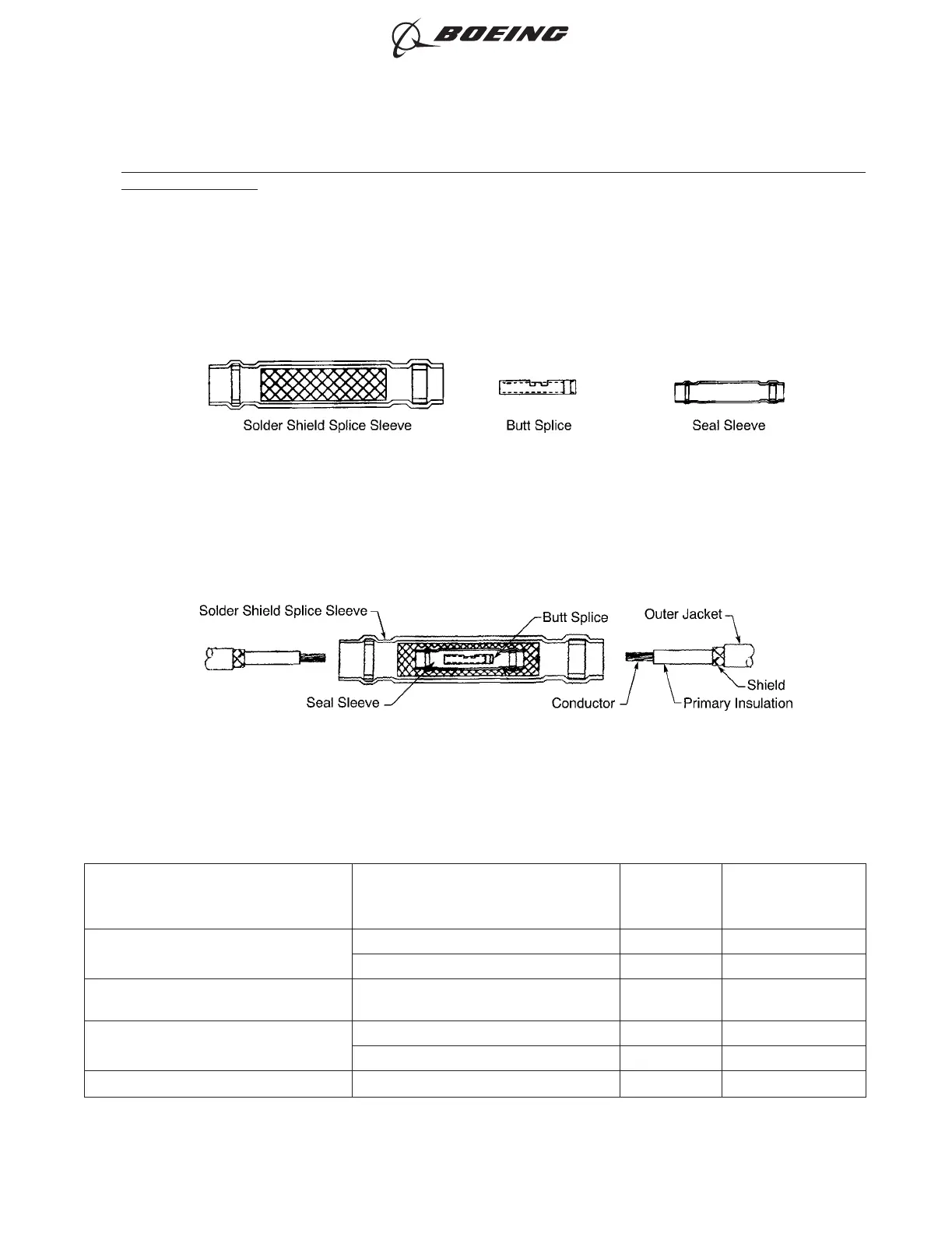
COMPONENTS OF THE RAYCHEM SOLDER SHIELD SPLICE KIT
Figure 263
ASSEMBLY CONFIGURATION OF THE SOLDER SHIELD SPLICE
Figure 264
ASSEMBLY OF SPLICES
707, 727-787
STANDARD WIRING PRACTICES MANUAL
20-30-12
Page 291
Jun 15/2021D6-54446
ECCN 9E991 BOEING PROPRIETARY - See title page for details