(1) Make a selection of a crimp tool from Table 8.
(2) Assemble the conductor splice.
Refer to:
• The applicable cable preparation configuration
• Paragraph 5.A. for the procedure to assemble the conductor splice.
(3) Align the center of the seal sleeve with the center of the splice assembly.
(4) Shrink the sleeve into its position. Refer to Subject 20-10-14 for the procedure to shrink a heat
shrinkable sleeve.
NOTE: If the sleeve has a tight fit on the conductor splice and cannot be moved on the
assembly, it is not necessary for the sleeve to shrink fully on the wire.
D. Assembly of the Shield Splice
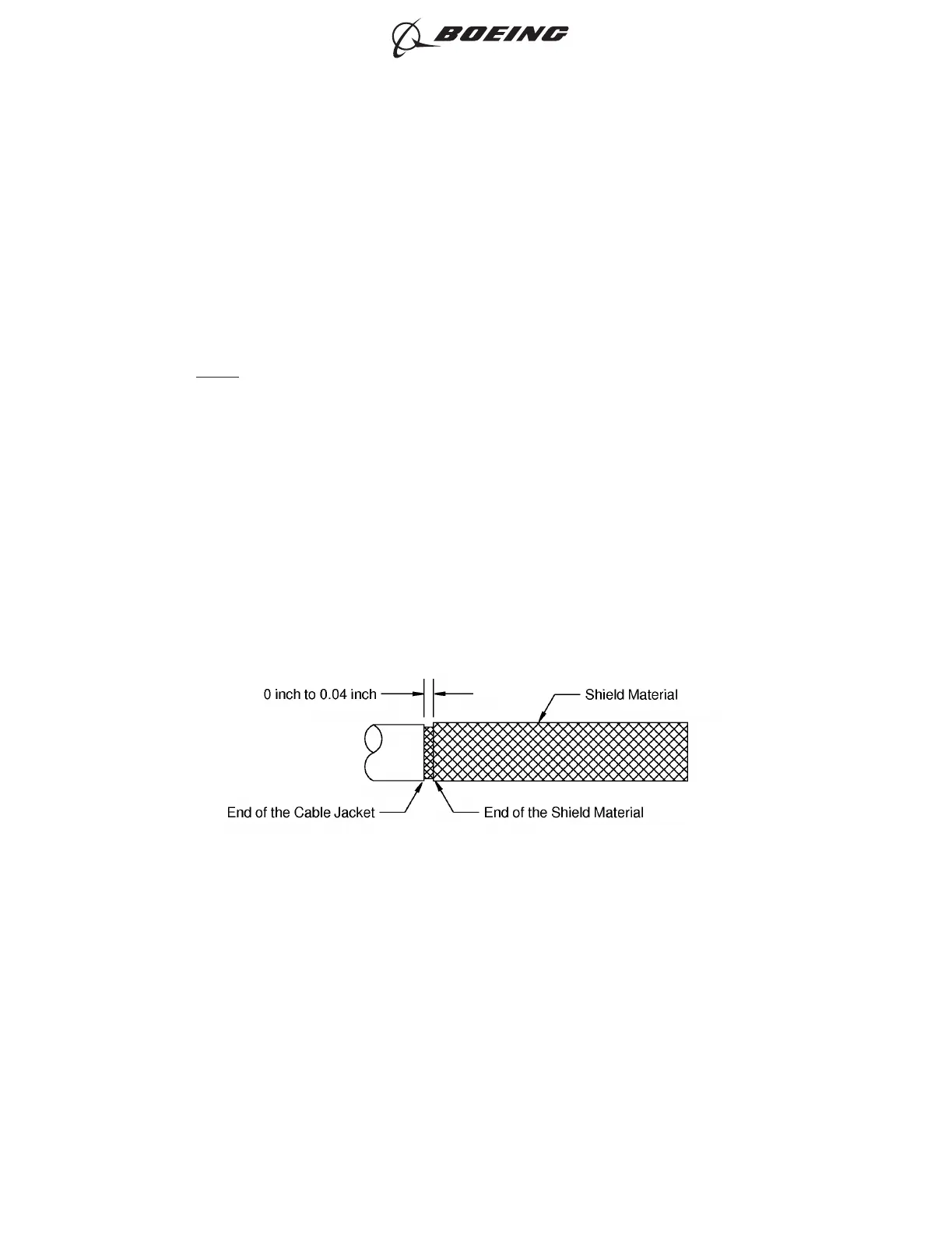
(1) On one end of the splice assembly, align the end of the shield material with the end of the cable
jacket. Refer to Figure 3.
Make sure that:
• The end of the shield material is not farther than 0.04 inch from the end of cable jacket
• The shield material does not make an overlap with the cable jacket.
(2) Twist the end of the shield material until it is tight against the shield of the cable.
(3) Install a solder sleeve at the end of the shield material.
Refer to:
POSITION OF THE SHIELD MATERIAL AT THE END OF THE CABLE JACKET
Figure 3
ASSEMBLY OF BACS52T SERIES SHIELDED SPLICE ASSEMBLIES
707, 727-787
STANDARD WIRING PRACTICES MANUAL
20-30-21
Page 22
Oct 15/2020D6-54446
ECCN 9E991 BOEING PROPRIETARY - See title page for details