Make sure that:
• The small end of the small solder sleeve is put on the cable first
• The large end of the large solder sleeve is put on the cable first.
(5) If the splice kit does not have seal inserts and the solder sleeves are the same size:
(a) Put these splice assembly components on Cable A in this sequence:
• The outer sleeve
• A solder sleeve
• The shield material.
Make sure that the small end of the solder sleeve is put on the cable first.
(b) Put the other solder sleeve on Cable B and Cable C.
Make sure that the small end of the solder sleeve is put on the cables first.
(6) Put a seal sleeve on Wire A1.
(7) Put a seal sleeve on Wire A2.
(8) Put Wire B3 and Wire C3 together.
(9) Put a seal sleeve on the Wire B3 and Wire C3 pair.
4. CABLE PREPARATION - SPECIAL CONFIGURATIONS
A. Kit Group P1N2, P2N2 or P3N2 - One Class 2 Cable, Isolated Shields to One Class 2 Cable,
Isolated Shields
For the conditions that are applicable for this procedure, refer to Paragraph 2.B..
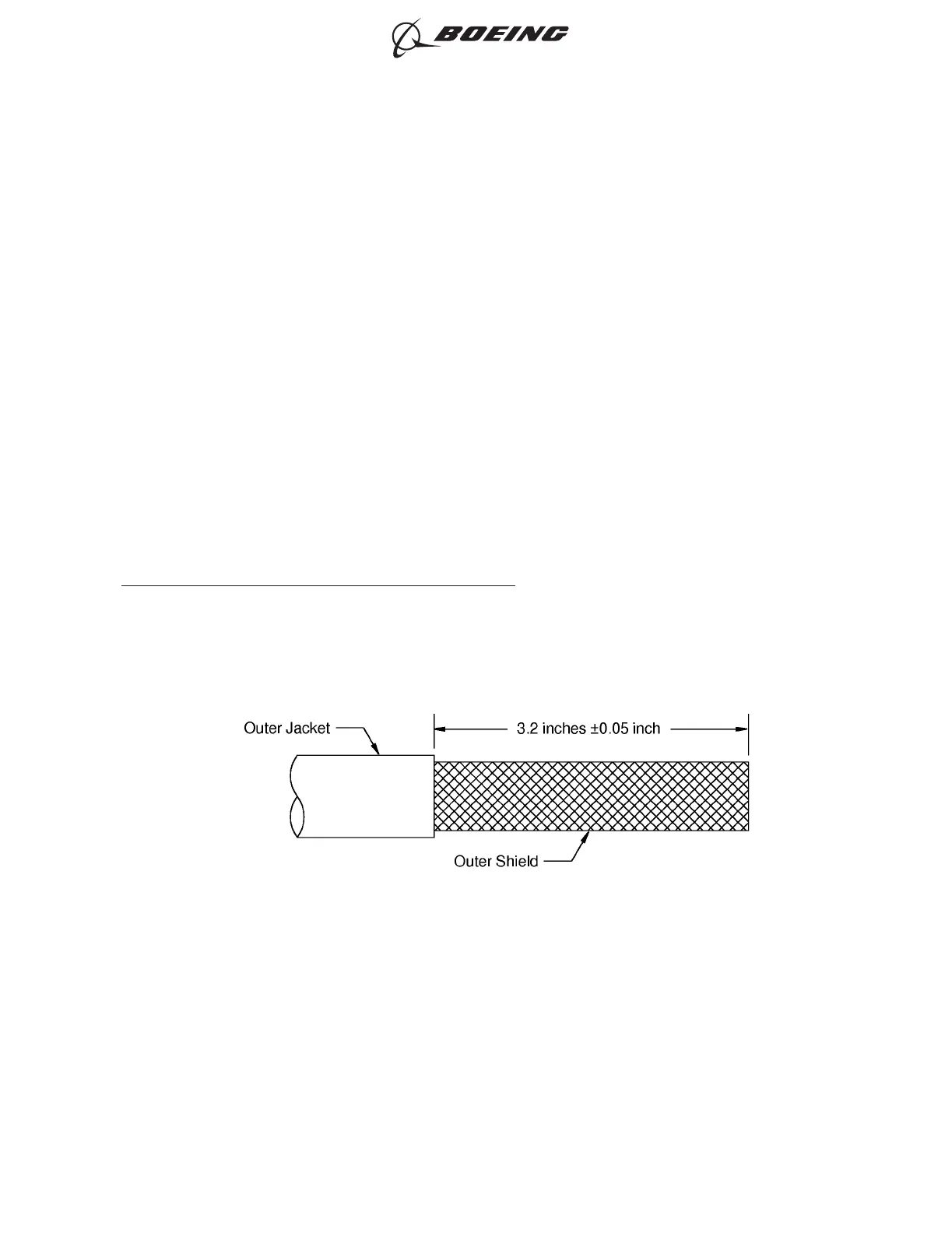
(1) Remove the necessary length of cable jacket from the end of the cable. Refer to Figure 28.
(2) Remove the necessary length of outer shield from the end of the cable. Refer to Figure 29.
OUTER CABLE JACKET REMOVAL
Figure 28
ASSEMBLY OF BACS52P SERIES AND D-150-0300 SERIES SHIELDED SPLICE ASSEMBLIES
707, 727-787
STANDARD WIRING PRACTICES MANUAL
20-30-20
Page 126
Jun 15/2021D6-54446
ECCN 9E991 BOEING PROPRIETARY - See title page for details