9. CONDUCTOR SPLICE CONFIGURATIONS FOR SHIELDED WIRES AND SHIELDED CABLES
A. Splice Assembly Configurations
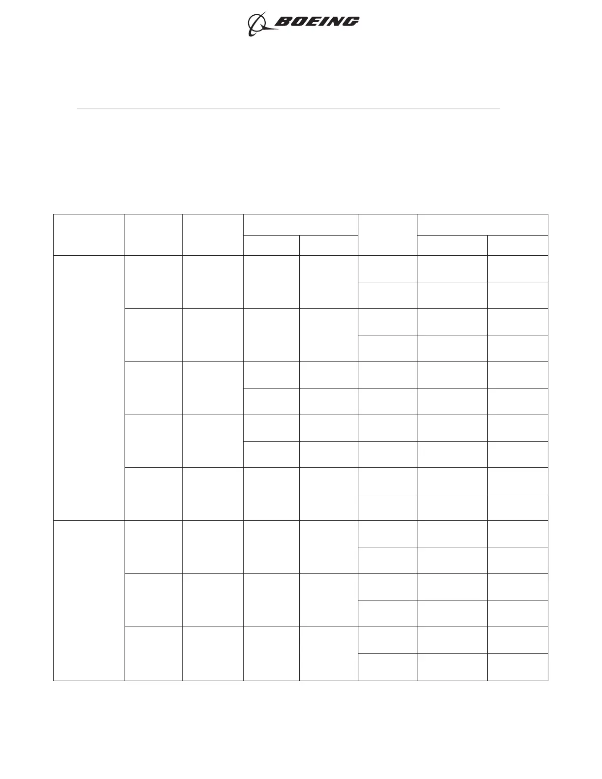
The splice assembly configurations in Table 91 are for the conductor splice of a sealed splice assembly
for shielded wire and shielded cable.
To calculate the CAU of the conductor, refer to Table 4.
Table 91
CONDUCTOR SPLICE ASSEMBLY CONFIGURATIONS
Maximum
Temperature
Grade
One End of
Splice
Assembly
Other End of
Splice
Assembly
CAU Range
Applicable
Condition
Splice Assembly
Minimum Maximum Components Procedure
B
One Wire One Wire 3 457
Fuel Vapor Tape
Paragraph
9.B.
No Fuel
Vapor
Tape
Paragraph
9.B.
One Wire Two Wires 3 457
Fuel Vapor Tape
Paragraph
9.C.
No Fuel
Vapor
Tape
Paragraph
9.C.
One or Two
Wires
One or Two
Wires
3 67
No Fuel
Vapor
Splice Kit
Paragraph
7.G.
3 457
No Fuel
Vapor
Sleeve
Paragraph
7.H.
One to Five
Wires
One to Five
Wires
3 457
No Fuel
Vapor
Sleeve
Paragraph
7.J.
19 67
No Fuel
Vapor
Splice Kit
Paragraph
7.I.
Two Wires Two Wires 3 457
Fuel Vapor Tape
Paragraph
9.D.
No Fuel
Vapor
Tape
Paragraph
9.D.
D
One Wire One Wire 5 138
Fuel Vapor Tape
Paragraph
9.E.
No Fuel
Vapor
Tape
Paragraph
9.E.
One Wire Two Wires 5 138
Fuel Vapor Tape
Paragraph
9.F.
No Fuel
Vapor
Tape
Paragraph
9.F.
Two Wires Two Wires 5 138
Fuel Vapor Tape
Paragraph
9.G.
No Fuel
Vapor
Tape
Paragraph
9.G.
ASSEMBLY OF SPLICES
707, 727-787
STANDARD WIRING PRACTICES MANUAL
20-30-12
Page 148
Jun 15/2021D6-54446
ECCN 9E991 BOEING PROPRIETARY - See title page for details