(2) Make a selection of a Temperature Grade D insulation tape from Table 52.
(3) Make a selection of a Temperature Grade D heat shrinkable sleeve from Table 51.
Make sure that the sleeve has the smallest diameter that can be put on the cable splice
assembly.
NOTE: For alternative heat shrinkable sleeves, refer to Subject 20-00-11.
(4) Cut the necessary length of the sleeve.
Make sure that the sleeve has a minimum overlap of 1 inch on each end of the outer jacket.
(5) Put the sleeve on the cable of one end of the splice assembly.
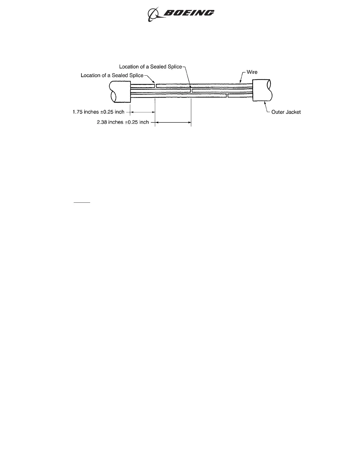
(6) Assemble the sealed splices on the wires in the cable.
Refer to Table 78 for an applicable sealed splice configuration on wire.
(7) Put two layers of insulation tape on the splice assembly.
(a) Tightly wind the first layer of tape on the splice assembly.
Make sure that the layer:
• Makes an overlap of 0.50 inch minimum to 0.75 inch maximum on each end of the
outer jacket
• Makes a 50 percent overlap.
(b) Tightly wind the second layer of tape on the splice assembly in the opposite direction of the
first layer.
Make sure that the layer:
• Starts where the first layer stops
• Stops where the first layer starts
• Makes a 50 percent overlap.
(8) Align the center of the sleeve with the center of the splice assembly.
Make sure that on each end of the splice assembly, the distance from the end of the layer of tape
to the end of the sleeve is 0.25 inch minimum.
(9) Shrink the sleeve in position. Refer to Subject 20-10-14.
CABLE PREPARATION
Figure 120
ASSEMBLY OF SPLICES
707, 727-787
STANDARD WIRING PRACTICES MANUAL
20-30-12
Page 147
Jun 15/2021D6-54446
ECCN 9E991 BOEING PROPRIETARY - See title page for details