(j) Crimp the Shield-Kon.
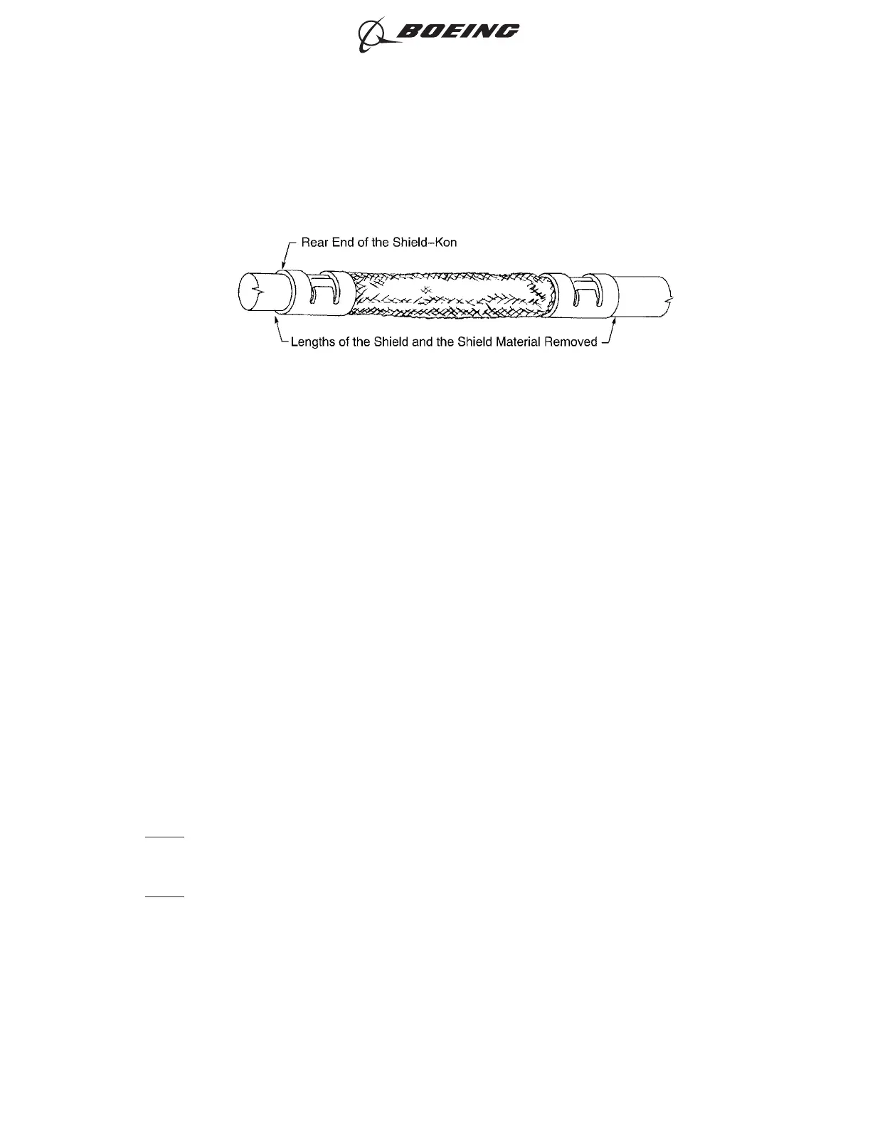
(k) Remove the shield and the shield sleeve material that extend farther than the rear end of
the Shield-Kon on each end of the shield splice. Refer to Figure 193.
(14) Tightly wind a layer of the tape on the splice assembly.
Make sure that the layer of tape:
• Starts 0.50 inch ±0.25 inch farther than the rear end of the Shield-Kon at one end of the
splice
• Stops 0.50 inch ±0.25 inch farther than the rear end of the Shield-Kon at the other end of
the splice
• Makes a 50 percent overlap.
(15) Tightly wind a second layer of the tape on the splice assembly.
Make sure that the layer of tape:
• Starts 1 inch minimum farther than where the first layer of tape stops
• Stops 1 inch minimum farther than where the first layer of tape starts
• Makes a 50 percent overlap.
(16) Assemble a lacing tape wire harness tie on each end of the splice assembly approximately 0.25
inch from the end of the tape. Refer to Subject 20-10-11.
Make sure that the Temperature Grade of the lacing tape is Temperature Grade B or higher.
C. Sealed Splice Configurations for Shielded Wire and Cable - One Shielded Wire to One Shielded
Wire - Shield Kons, Tape, Sleeve
NOTE: The larger diameter Shield-Kons are no longer manufactured. For an alternative procedure to
assemble a splice for larger diameter shielded wire, refer to Paragraph 13.C. for the assembly
of a sealed splice with shield termination rings, shield terminator bands, tape and sleeve.
NOTE: If the correct diameter Shield-Kons are available, this procedure can be used:
For the conditions that are applicable for:
• The repair of a wire or a cable with a splice, refer to Subject 20-10-13
• The selection of the correct sealed splice configuration, refer to Paragraph 1.C.
SHIELD SPLICE ASSEMBLY
Figure 193
ASSEMBLY OF SPLICES
707, 727-787
STANDARD WIRING PRACTICES MANUAL
20-30-12
Page 236
Jun 15/2021D6-54446
ECCN 9E991 BOEING PROPRIETARY - See title page for details