(12) Shrink the short sleeve into position. Refer to Subject 20-10-14.
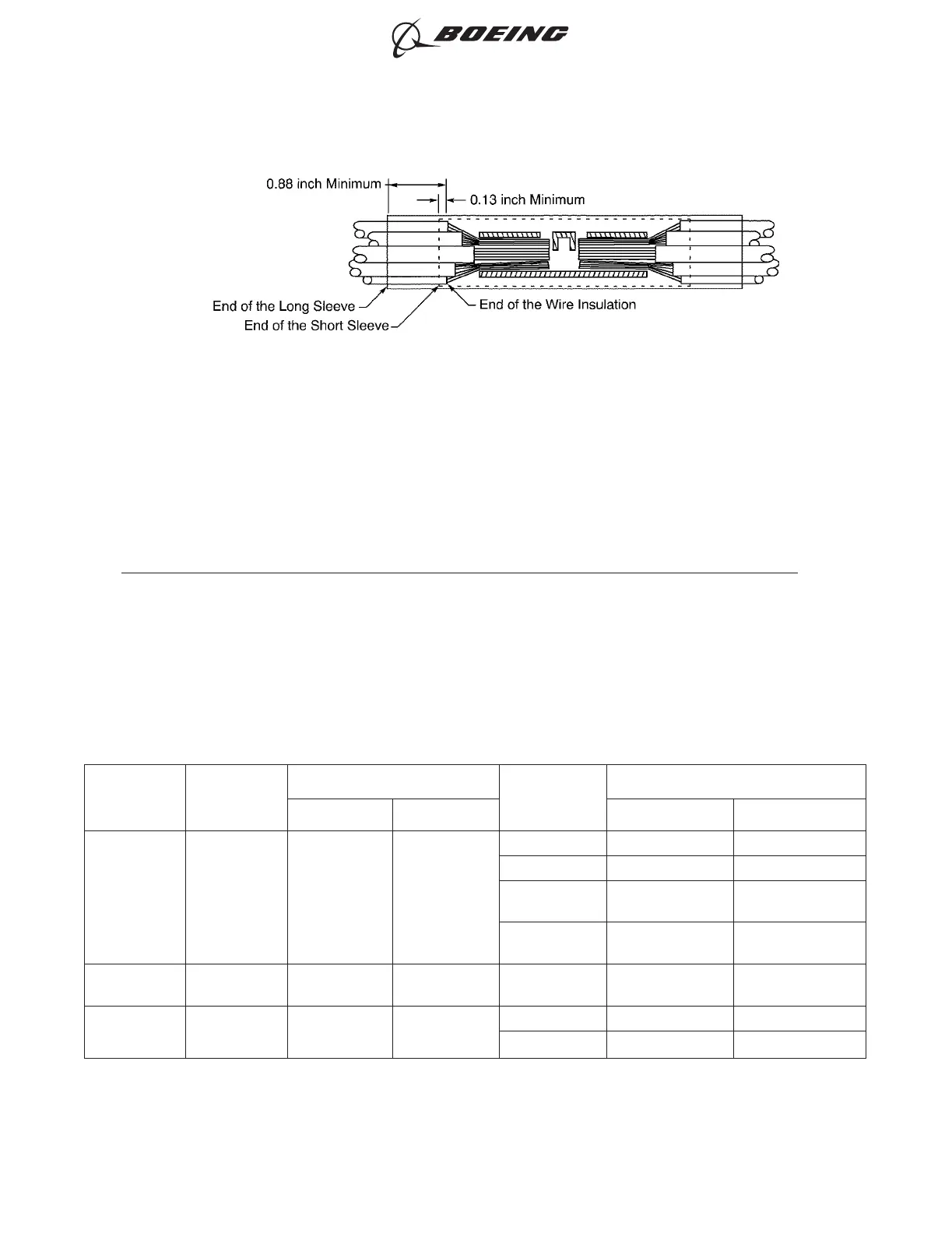
(13) Align the center of the long sleeve with the center of the splice. Refer to Figure 38.
Make sure that the long sleeve makes a 0.88 inch minimum overlap with the wire insulation on
each end of the splice assembly.
(14) Shrink the long sleeve into position. Refer to Subject 20-10-14.
7. SEALED SPLICE CONFIGURATIONS FOR UNSHIELDED WIRES AND UNSHIELDED CABLES
A. Splice Assembly Configurations
For the conditions that are applicable for:
• The repair of a wire or a cable with a splice, refer to Subject 20-10-13
• The selection of the correct sealed splice configuration, refer to Paragraph 1.C.
To calculate the CAU of the conductor, refer to Table 4.
Table 66
SEALED SPLICE ASSEMBLY CONFIGURATIONS
One End of
Splice
Assembly
Other End of
Splice
Assembly
CAU Range
Applicable
Condition
Splice Assembly
Minimum Maximum Configuration Procedure
One Wire One Wire 3 457
Fuel Vapor Tape, Ties Paragraph 7.B.
No Fuel Vapor Tape, Ties Paragraph 7.B.
Fuel Vapor
Sealant, Sleeve,
Ties
Paragraph 7.C.
No Fuel Vapor
Sealant, Sleeve,
Ties
Paragraph 7.C.
One Wire One Wire - - No Fuel Vapor
Sleeves - Resistor
or Diode
Paragraph 7.M.
One Wire Two Wires 3 457
Fuel Vapor Tape, Ties Paragraph 7.D.
No Fuel Vapor Tape, Ties Paragraph 7.D.
POSITION OF THE SLEEVES ON THE SPLICE ASSEMBLY
Figure 38
ASSEMBLY OF SPLICES
707, 727-787
STANDARD WIRING PRACTICES MANUAL
20-30-12
Page 79
Feb 15/2021D6-54446
ECCN 9E991 BOEING PROPRIETARY - See title page for details