• The large solder sleeve
• The seal sleeve.
Make sure that:
• The small end of the small solder sleeve is put on the cable first
• The large end of the large solder sleeve is put on the cable first.
(5) If the splice kit does not have seal inserts and the solder sleeves are the same size put these
splice assembly components on Cable A in this sequence:
• The outer sleeve
• A solder sleeve
• The shield material
• The other solder sleeve
• The seal sleeve.
Make sure that:
• The small end of the first solder sleeve is put on the cable first.
• The large end of the second solder sleeve is put on the cable first.
(6) Put a seal sleeve on Wire A.
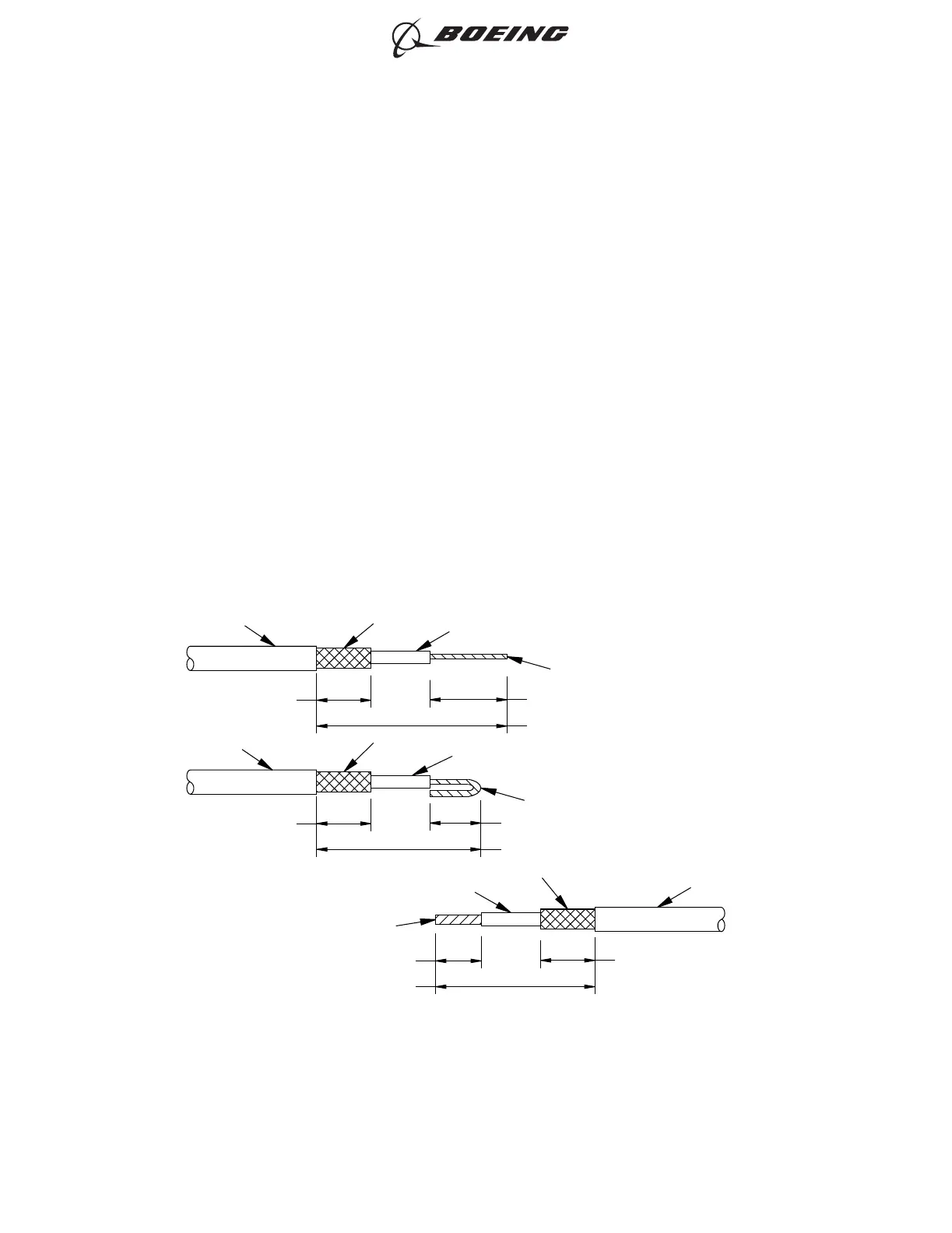
C. Kit Group P1N1, P2N1, P3N1 or P4N1 - One Class 1 Cable to One Class 1 Cable
For the conditions that are applicable for this procedure, refer to Paragraph 2.B..
Refer to Figure 32.
CONDUCTOR
INSULATION
SHIELD
1.5 ±0.05 INCHES
0.5 ±0.05 INCH
CABLE B
JACKET
0.3 ±0.05 INCH
INSULATION
SHIELD
CABLE A
CABLE A
CONDUCTOR
1.5 ±0.05 INCHES
0.3 ±0.05 INCH0.5 ±0.05 INCH
JACKET
INSULATION
SHIELD
CONDUCTOR
JACKET
0.5 ±0.05 INCH
1.8 ±0.05 INCHES
0.6 ±0.05 INCH
2449595 S00061545759_V2
ONE CLASS 1 CABLE TO ONE CLASS 1 CABLE
Figure 32
ASSEMBLY OF BACS52P SERIES AND D-150-0300 SERIES SHIELDED SPLICE ASSEMBLIES
707, 727-787
STANDARD WIRING PRACTICES MANUAL
20-30-20
Page 132
Feb 15/2022D6-54446
ECCN 9E991 BOEING PROPRIETARY - See title page for details