F. Sealed Splice Configurations for Unshielded Wires and Cables - One Wire to Two Wires -
D-436-58 Splice Kit - Wires from Both Ends of the Splice
This procedure is applicable when it is specified.
Table 72
INSULATION REMOVAL LENGTH
Splice Part Number
Insulation Removal Length L
(inch)
Target Tolerance
D-609-04 0.28 ±0.03
(1) Make a selection of a crimp tool from Table 39 for Raychem D-609-0() parallel splices.
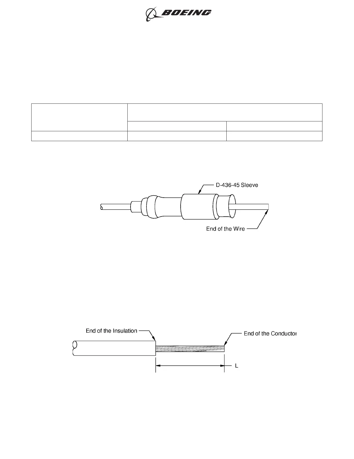
(2) Put the small end of the sleeve on the single wire. Refer to Figure 57.
Make sure that the larger end of the sleeve points toward the end of the wire.
(3) Remove the necessary length of insulation from the end of each wire.
Refer to:
• Figure 58
• Table 72 for the insulation removal length
• Subject 20-00-15 for the insulation removal procedures.
POSITION OF THE SLEEVE ON THE WIRE
Figure 57
INSULATION REMOVAL LENGTH
Figure 58
ASSEMBLY OF SPLICES
707, 727-787
STANDARD WIRING PRACTICES MANUAL
20-30-12
Page 96
Feb 15/2021D6-54446
ECCN 9E991 BOEING PROPRIETARY - See title page for details