(4) Put the parallel splice in the crimp tool.
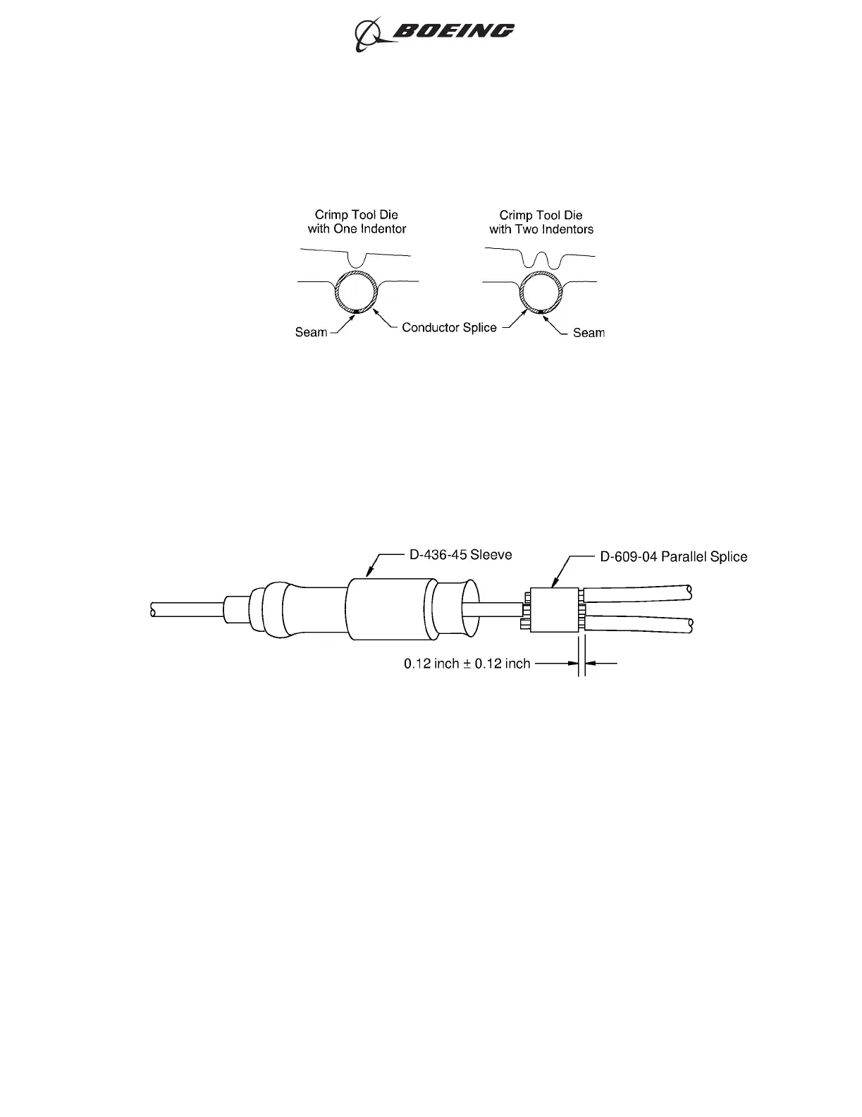
(5) If the splice has a seam, align the seam opposite the indenter. Refer to Figure 59.
(6) Hold the splice in position with light pressure.
(7) Put the single wire in one end of the parallel splice and put the other two wires into the other end
of the splice. Refer to Figure 60.
Make sure that the distance from the end of the wire insulation to the edge of the parallel splice is
0.12 inch ±0.12 inch.
(8) Crimp the splice.
(9) Push the sleeve forward on the splice assembly.
Make sure that the large part of the sleeve is aligned with the center of the parallel splice.
(10) Shrink the sleeve into its position.
Refer to:
• Figure 61
• Subject 20-10-14.
POSITION OF THE PARALLEL SPLICE IN THE CRIMP TOOL
Figure 59
POSITION OF EACH WIRE IN THE PARALLEL SPLICE
Figure 60
ASSEMBLY OF SPLICES
707, 727-787
STANDARD WIRING PRACTICES MANUAL
20-30-12
Page 97
Feb 15/2021D6-54446
ECCN 9E991 BOEING PROPRIETARY - See title page for details