B. Splice Assembly Cable Preparation
(1) Make a selection of a splice assembly configuration from Table 7.
NOTE: Table 7 gives the special configurations of cable preparation.
(2) If the wiring configuration and the splice kit are not specified in Table 7, make a selection of a
splice assembly configuration from Table 6.
NOTE: Table 6 gives the standard configurations of cable preparation.
(3) If a build-up sleeve is specified, put a 1.0 inch ±0.1 inch length of the specified sleeve on the
applicable wiring. Refer to Table 4.
(4) Prepare the end of each cable.
Refer to:
• The applicable splice assembly configuration
• Subject 20-00-15 for the procedure to remove the cable jacket
• Subject 20-00-15 for the procedure to remove the wire insulation.
(5) If it is specified, fold the conductor or conductors back.
(6) If a filler wire is specified:
(a) Cut a 1.0 inch to 2.0 inch length of the filler wire.
(b) Remove 0.30 inch ±0.05 inch of the insulation from the end of the wire. Refer to
Subject 20-00-15.
C. Assembly of the Conductor Splice
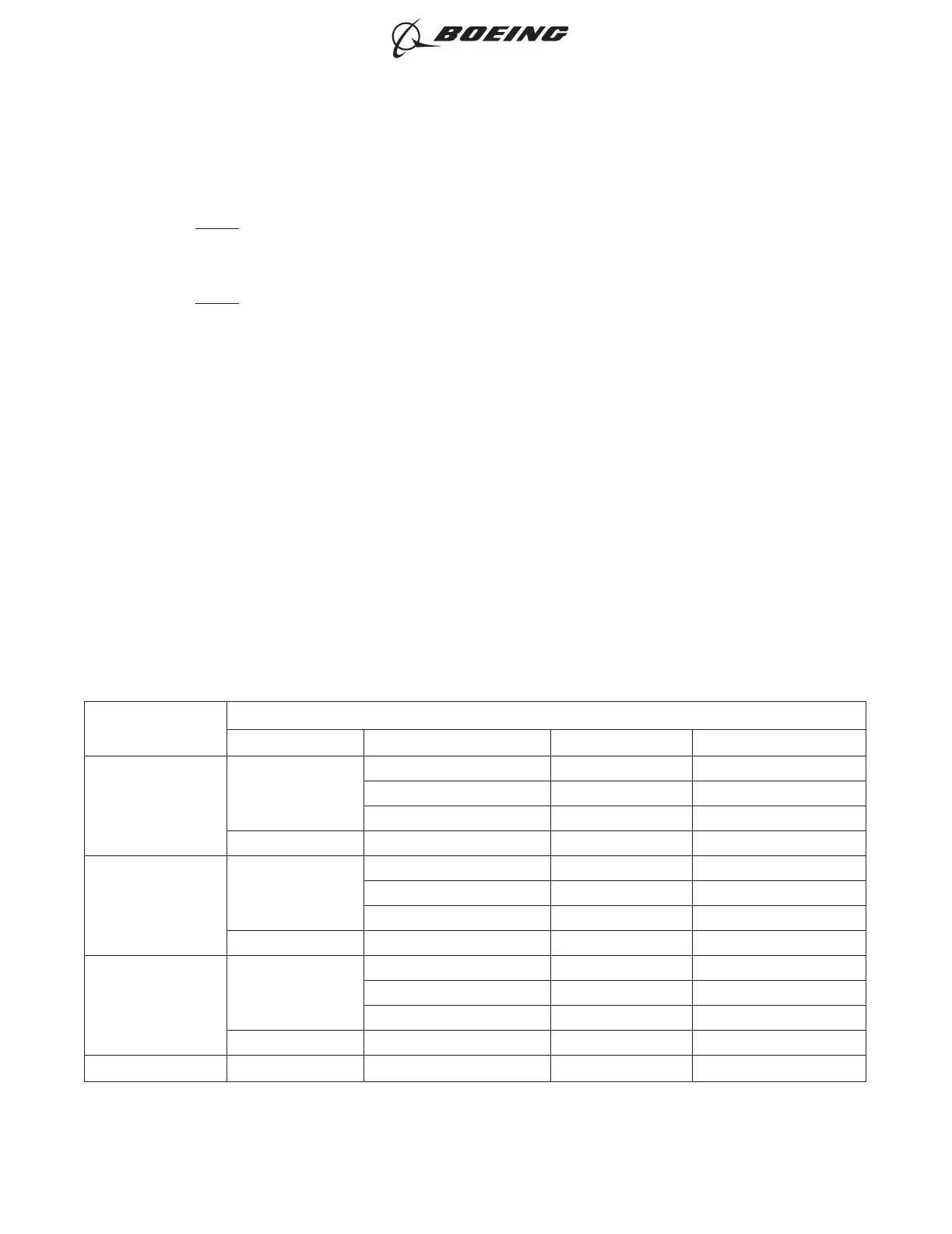
Table 8
CONDUCTOR SPLICE CRIMP TOOLS
Crimp Barrel Size
Crimp Tool
Type Basic Unit Die or Nest Color Supplier
26-20
Hand
AD-1377 Red Tyco
ST956C Red Boeing
ST956D Red Boeing
Power PMTB-232 Red Daniels
20-16
Hand
AD-1377 Blue Tyco
ST956C Blue Boeing
ST956D Blue Boeing
Power PMTB-232 Blue Daniels
16-12
Hand
AD-1377 Yellow Tyco
ST956C Yellow Boeing
ST956D Yellow Boeing
Power PMTB-232 Yellow Daniels
12-10 Hand 46447 12-10 AMP
ASSEMBLY OF BACS52T SERIES SHIELDED SPLICE ASSEMBLIES
707, 727-787
STANDARD WIRING PRACTICES MANUAL
20-30-21
Page 21
Oct 15/2020D6-54446
ECCN 9E991 BOEING PROPRIETARY - See title page for details