(l) Install the identification sleeve on the assembly in accordance with Subject 20-10-14. Refer
to Figure 1. Make sure the identification sleeve is approximately centered on the DWP-125
sleeve
15. SEALED SPLICE CONFIGURATIONS WITH SOLDER SLEEVE SHIELD SPLICES FOR SHIELDED WIRE
AND SHIELDED CABLE
A. Splice Assembly Configurations
For the conditions that are applicable for:
• The repair of a wire or a cable with a splice, refer to Subject 20-10-13
• The selection of the correct sealed splice configuration, refer to Paragraph 1.C.
Table 140
SPLICE ASSEMBLY CONFIGURATIONS
One End of Splice
Assembly
Other End of Splice
Assembly
Quantity of
Conductor
Splices
Applicable
Condition
Splice Assembly
Configuration Procedure
One Shielded Wire One Shielded Wire 1 No Fuel Vapor Tape, Sleeve Paragraph 15.B.
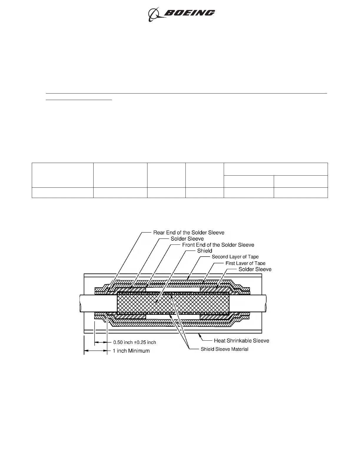
B. Sealed Splice Configurations for Shielded Wire and Cable - Solder Sleeve Shield Splice - One
Shielded Wire to One Shielded Wire, Solder Sleeves, Tape, Sleeve
Refer to Figure 295.
(1) Make a selection of a Temperature Grade B shield sleeve material from Table 57.
SPLICE OF THE SHIELD
Figure 295
ASSEMBLY OF SPLICES
707, 727-787
STANDARD WIRING PRACTICES MANUAL
20-30-12
Page 332
Jun 15/2021D6-54446
ECCN 9E991 BOEING PROPRIETARY - See title page for details