Table 139
Splice Part Numbers for In-Line Resistors AND DIODES
Resistor or Diode Wire Gauge Splice
RWR80( ) 26-20 D-609-06
(a) Prepare the end of the cables in accordance with Figure 2 and Subject 20-30-12.
(b) Put the BACS13DF4 solder shield sleeve on one of the cables.
NOTE: BACS13DF4 can be obtained from shielded cable splice kit part number
BACS52R1T2 or D-150-0174.
(c) Move the sleeve away from the end of the cable.
(d) Make an identification sleeve with the resistor or diode equipment number in accordance
with the Subject 20-10-11.
(e) Put the Identification sleeve on to the wire that does not have the shield sleeve.
(f) Move the identification sleeve away from the end of the cable.
(g) Put a 2.15 ±0.13 inch length of smallest diameter DWP-125 sleeve on the cable that has the
identification sleeve.
(h) Install the applicable splice on to each end of the resistor or diode in accordance with Table
2/SEALED SPLICE CONFIGURATIONS FOR UNSHIELDED WIRE AND UNSHIELDED
CABLE and Subject 20-30-12
(i) Install the other end of the splices on to the center conductor if the coax cables in
accordance with Subject 20-30-12. SeeFigure 1.
(j) Install the DWP-125 heat shrinkable sleeve on to the splice assembly in accordance with
Subject 20-10-14. Make sure that”
1) The sleeve is approximately centered on the assembly.
2) The sleeve is not on the shield of the cable.
(k) Install a BACS13DF4 solder sleeve shield onto the assembly in accordance with Figure 1
and Subject 20-30-19. Make sure the sleeve is approximately centered on the assembly.
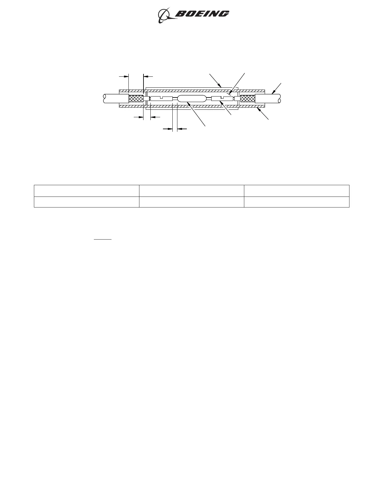
0.2 inch ±0.1 inch
0.13 inch +0.13 inch, -0.0 inch
0.38 inch ±0.05 inch
Identification Sleeve
Resistor or Diode
Splice
BACS13DF4 Solder
Shield Sleeve
Shielded Cable
DWP-125 Heat Shrinkable Sleeve
2579053 S0000620824_V1
Assembling In-Line Resistors or Diodes
Figure 294
ASSEMBLY OF SPLICES
707, 727-787
STANDARD WIRING PRACTICES MANUAL
20-30-12
Page 331
Jun 15/2021D6-54446
ECCN 9E991 BOEING PROPRIETARY - See title page for details