(4) Put a seal sleeve on Wire A1.
D. Kit Groups T1( )1, T2( )1, T3( )1 or T4( )1 - One Class 2 Cable to One Class 3 Cable
For the conditions that are applicable for this procedure, refer to Paragraph 2.B..
Refer to Figure 10.
Table 12
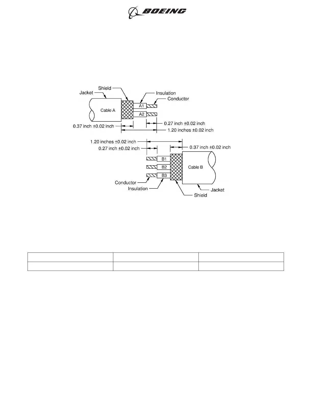
CONNECTIONS
Wires Connection Wires Connected to
A1 and A2 Splice B1, B2 and B3
(1) Remove approximately 0.05 inch from each end of the shield material with a pair of scissors or an
equivalent tool.
(2) Put these splice assembly components on Cable A in this sequence:
• The outer sleeve
• A solder sleeve
• The shield material
Make sure that the small end of the solder sleeve is put on the cable first.
(3) Put the other solder sleeve on Cable B.
Make sure that the small end of the solder sleeve is put on the cable first.
(4) Put a seal sleeve on the Wire A1 and A2 pair.
ONE CLASS 2 CABLE TO ONE CLASS 3 CABLE
Figure 10
ASSEMBLY OF BACS52T SERIES SHIELDED SPLICE ASSEMBLIES
707, 727-787
STANDARD WIRING PRACTICES MANUAL
20-30-21
Page 29
Jun 15/2021D6-54446
ECCN 9E991 BOEING PROPRIETARY - See title page for details