Table 31
CONNECTIONS
Wire Connection Wire conneted to
A Splice B and C
(1) Remove approximately 0.05 inch from each end of the shield material with a pair of scissors or an
equivalent tool.
NOTE: The shield material has fused ends that hold the ends of the strands of the shield
together.
(2) Put these splice assembly components on Cable A in this sequence:
• The outer sleeve
• A solder sleeve
• The shield material
Make sure that the small end of the solder sleeve is put on the cable first.
(3) Put the other solder sleeve on Cable B and Cable C.
Make sure that the small end of the solder sleeve is put on the cables first.
(4) Put a seal sleeve on Wire A.
B. Kit Group T1( ) 1, T2( ) 1, T3( ) 1 or T4( ) 1 - One Class 1 Cable to One Class 1 Cable
For the conditions that are applicable for this procedure, refer to Paragraph 2.B..
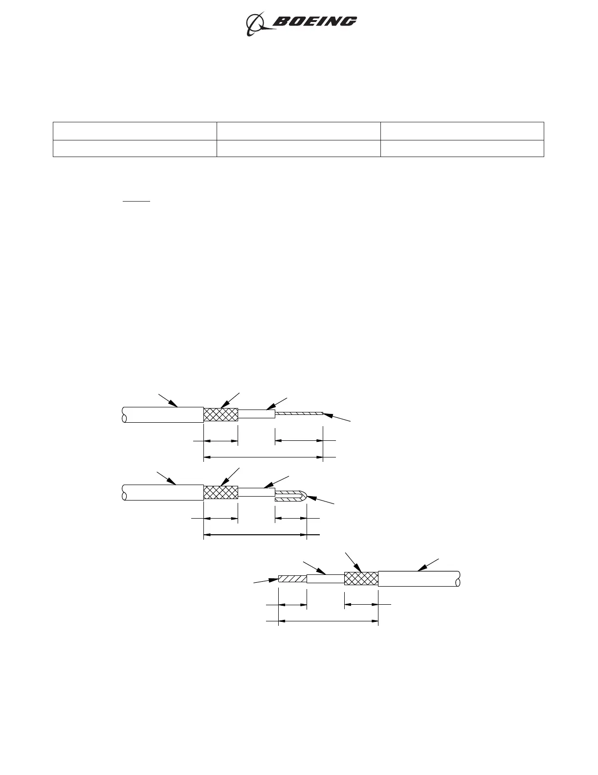
Refer to Figure 30.
CONDUCTOR
INSULATION
SHIELD
1.07 ±0.02 INCHES
0.37 ±0.02 INCH
CABLE B
JACKET
0.27 ±0.02 INCH
INSULATION
SHIELD
CABLE A
CABLE A
CONDUCTOR
1.07 ±0.02 INCHES
0.27 ±0.02 INCH
0.37 ±0.02 INCH
JACKET
INSULATION
SHIELD
CONDUCTOR
JACKET
0.37 ±0.02 INCH
1.37 ±0.02 INCHES
0.57 ±0.02 INCH
2449847 S00061545800_V2
ONE CLASS 1 CABLE TO ONE CLASS 1 CABLE
Figure 30
ASSEMBLY OF BACS52T SERIES SHIELDED SPLICE ASSEMBLIES
707, 727-787
STANDARD WIRING PRACTICES MANUAL
20-30-21
Page 77
Feb 15/2022D6-54446
ECCN 9E991 BOEING PROPRIETARY - See title page for details