This Subject gives the procedures to assemble terminals and splices when:
• The wire size is smaller than the crimp barrel of the terminal or splice
• The size of the wire insulation is smaller than the insulation grip of the terminal or splice
• The terminal or splice is assembled with more than one wire.
1. CIRCULAR AREA UNITS
A. Circular Area Units of Conductors
For the Circular Area Units (CAU) of a conductor, refer to Table 1.
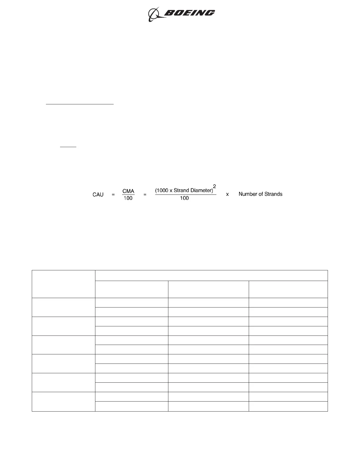
CAU can be calculated if the Circular Mil Area (CMA) of a conductor is known. Refer to Figure 1.
NOTE: The circular mils of a conductor can be found in all wire tables. If the tables are not available,
the CMA can be calculated. Refer to Figure 1.
Table 1
CAU OF CONDUCTORS
Wire Size
(AWG)
Conductor
Type
Maximum O.D.
(inch)
CAU
32
Solid 0.008 0.6
Stranded 0.009 0.6
30
Solid 0.010 1
Stranded 0.012 1
28
Solid 0.013 1.6
Stranded 0.015 1.6
26
Solid 0.016 3
Stranded 0.019 3
24
Solid 0.020 5
Stranded 0.024 5
22
Solid 0.025 8
Stranded 0.030 8
CIRCULAR AREA UNITS OF A CONDUCTOR
Figure 1
ASSEMBLY OF TERMINALS AND SPLICES UNDER SPECIAL CONDITIONS
707, 727-787
STANDARD WIRING PRACTICES MANUAL
20-30-22
Page 2
Oct 15/2015D6-54446
ECCN 9E991 BOEING PROPRIETARY - See title page for details