Make sure that the shield sleeve material has the smallest diameter that can go on the wire.
NOTE: For alternative shield sleeve materials, refer to Subject 20-00-11.
(2) Make a selection of a Temperature Grade B or higher insulation tape from Table 52.
(3) Make a selection of two solder sleeves from Table 55.
(4) Prepare the wire.
Refer to:
• Figure 296
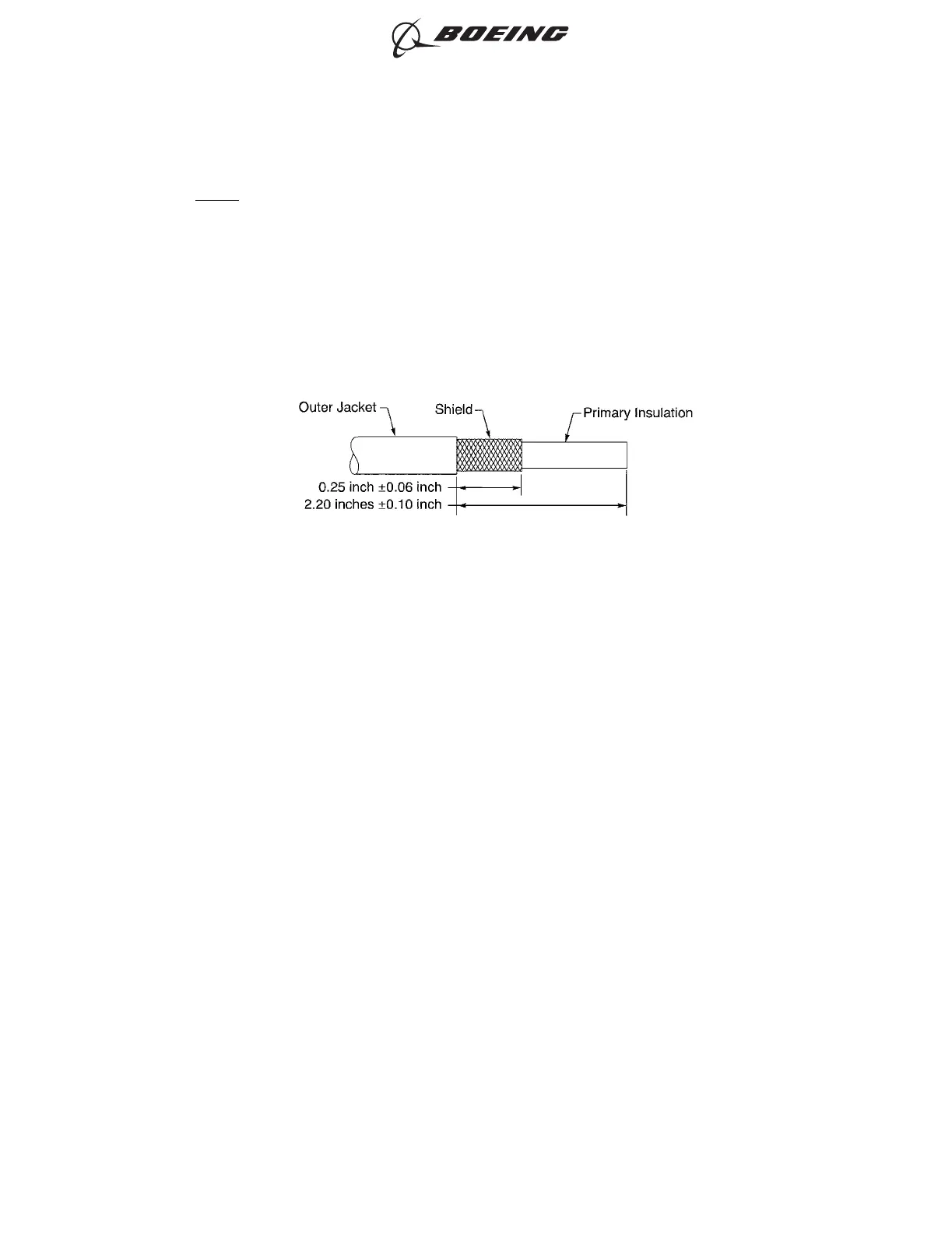
• Subject 20-00-15 for the outer jacket removal procedures.
(a) Remove 2.20 inches ±0.10 inch of the outer jacket from the end of each wire.
(b) Remove the necessary length of shield from the wire that makes the distance from the end
of the shield to the end of the jacket equal to 0.25 inch ±0.06 inch.
(5) Cut the necessary length of the shield sleeve material.
Make sure that length is sufficient to extend from the end of the outer jacket on one wire to the
end of the outer jacket on the other wire.
(6) Cut the necessary length of the heat shrinkable sleeve.
Make sure that length is sufficient to extend a minimum of 1 inch farther than the rear end of the
solder sleeve on each wire after the solder sleeves are installed.
(7) Clean the jacket with isopropyl alcohol.
Make sure:
• To clean the area from each end of the jacket to a minimum of 3 inches to the rear
• That the cleaned area is dry.
(8) Put the heat shrinkable sleeve on one end of the wire.
(9) Put a solder sleeve on each end of the wire.
(10) Put the shield sleeve material on one end of the wire.
(11) Make a selection of an applicable Temperature Grade B conductor splice configuration for one
wire to one wire. Refer to Paragraph 9.A.
(12) Assemble the conductor splice. Refer to the applicable procedure given in Paragraph 9.A.
WIRE PREPARATION
Figure 296
ASSEMBLY OF SPLICES
707, 727-787
STANDARD WIRING PRACTICES MANUAL
20-30-12
Page 333
Jun 15/2021D6-54446
ECCN 9E991 BOEING PROPRIETARY - See title page for details