(b) Shrink the short sleeve in position. Refer to Subject 20-10-14.
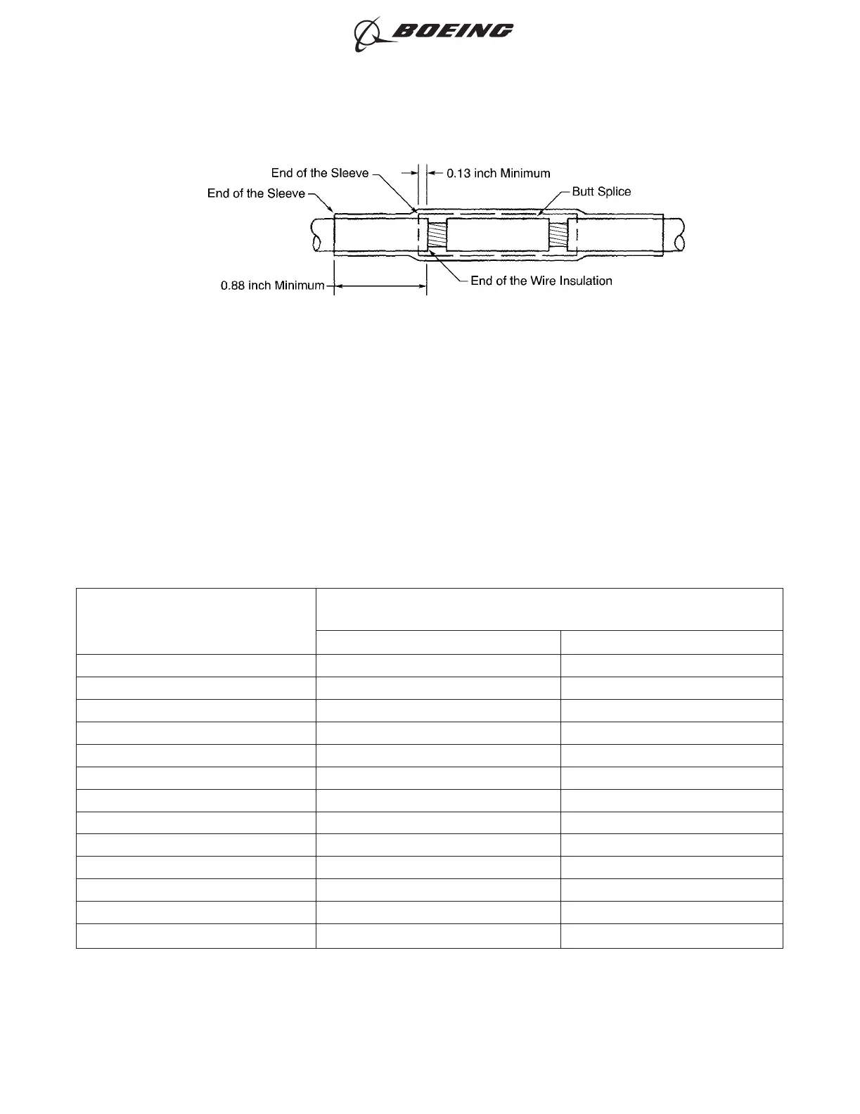
(c) Align the center of the long sleeve with the center of the splice. Refer to Figure 34.
Make sure that the long sleeve makes a 0.88 inch minimum overlap with the wire insulation
on each end of the splice assembly.
(d) Shrink the long sleeve into position. Refer to Subject 20-10-14.
E. Unsealed Butt Splice Configurations - More Than One Wire to More Than One Wire - Butt Splice,
Sleeves
Table 65
INSULATION REMOVAL LENGTH
Splice Part Number
Insulation Removal Length L
(inch)
Target Tolerance
BACT12C12 0.47 ±0.03
BACT12C4 0.53 ±0.03
BACT12C4NK 0.47 ±0.03
BACT12C6 0.53 ±0.03
BACT12C6NK 0.53 ±0.03
BACT12C8 0.47 ±0.03
BACT12C8NK 0.53 ±0.03
D-609-06 0.28 ±0.03
D-609-07 0.28 ±0.03
D-609-08 0.28 ±0.03
NAS1387-4 0.28 ±0.03
NAS1387-5 0.28 ±0.03
NAS1387-6 0.28 ±0.03
POSITION OF THE SLEEVES ON THE SPLICE ASSEMBLY WITH AWG 8 AND LARGER WIRE
Figure 34
ASSEMBLY OF SPLICES
707, 727-787
STANDARD WIRING PRACTICES MANUAL
20-30-12
Page 76
Feb 15/2021D6-54446
ECCN 9E991 BOEING PROPRIETARY - See title page for details