(9) Crimp the splice.
(10) Make a selection of a Temperature Grade B heat shrinkable sleeve from Table 51.
Make sure that the sleeve has the smallest diameter that can be put on the splice assembly.
NOTE: For alternative heat shrinkable sleeves, refer to Subject 20-00-11.
(11) Cut the necessary length of the sleeve. Refer to Figure 22.
NOTE: The necessary length is a minimum of 2.0 inches plus the length of the splice.
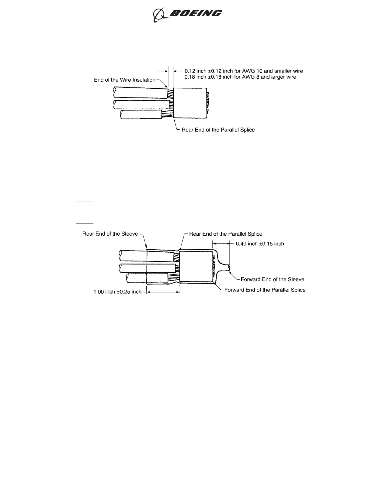
(12) Put the sleeve on the splice assembly. Refer to Figure 22.
Make sure that:
• The distance from the forward end of the sleeve to the forward end of the splice is 0.40 inch
±0.15 inch
• The distance from the rear end of the sleeve to the rear end of the splice is 1.00 inch ±0.25
inch.
(13) Shrink the sleeve into position. Refer to Subject 20-10-14.
(14) After the wire harness assembly is installed, examine the splice assembly.
Make sure that:
• The start of each branch is near the top side of the harness
• The end of each splice is pointed up
POSITION OF EACH WIRE IN THE PARALLEL SPLICE
Figure 21
POSITION OF THE SLEEVE ON THE SPLICE ASSEMBLY
Figure 22
ASSEMBLY OF SPLICES
707, 727-787
STANDARD WIRING PRACTICES MANUAL
20-30-12
Page 65
Feb 15/2021D6-54446
ECCN 9E991 BOEING PROPRIETARY - See title page for details