Make sure to:
• Put the end of the sleeve with the wire seal on the wires first
• Put one wire in each hole of the wire seal.
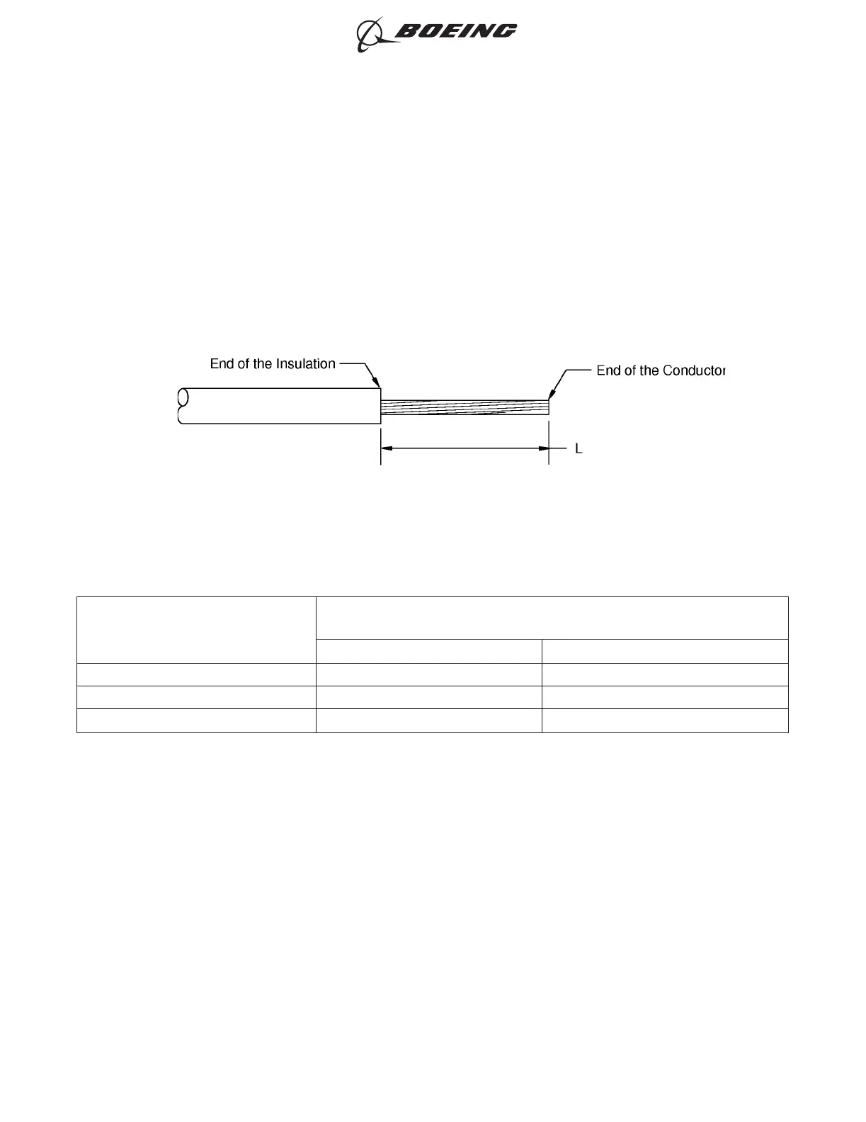
(7) Remove the necessary length of insulation from the end of each wire.
Refer to:
• Figure 9
• Table 59 for the insulation removal length
• Subject 20-00-15 for the insulation removal procedures.
Table 59
INSULATION REMOVAL LENGTH
Splice Part Number
Insulation Removal Length L
(inch)
Target Tolerance
D-609-04 0.28 ±0.03
D-609-05 0.28 ±0.03
D-609-14 0.28 ±0.03
(8) Put the splice in the crimp tool.
(9) Hold the splice in position with light pressure.
(10) Put each wire in the same end of the splice. Refer to Figure 10.
Make sure that the distance from the end of the wire insulation to the rear end of the splice is:
• 0.12 inch ±0.12 inch for wires AWG 10 and smaller
• 0.18 inch ±0.18 inch for wires AWG 8 and larger.
INSULATION REMOVAL LENGTH
Figure 9
ASSEMBLY OF SPLICES
707, 727-787
STANDARD WIRING PRACTICES MANUAL
20-30-12
Page 56
Feb 15/2021D6-54446
ECCN 9E991 BOEING PROPRIETARY - See title page for details