Make sure to:
• Put the end of the sleeve with the wire seal on the wires first
• Put one wire in each hole of the wire seal.
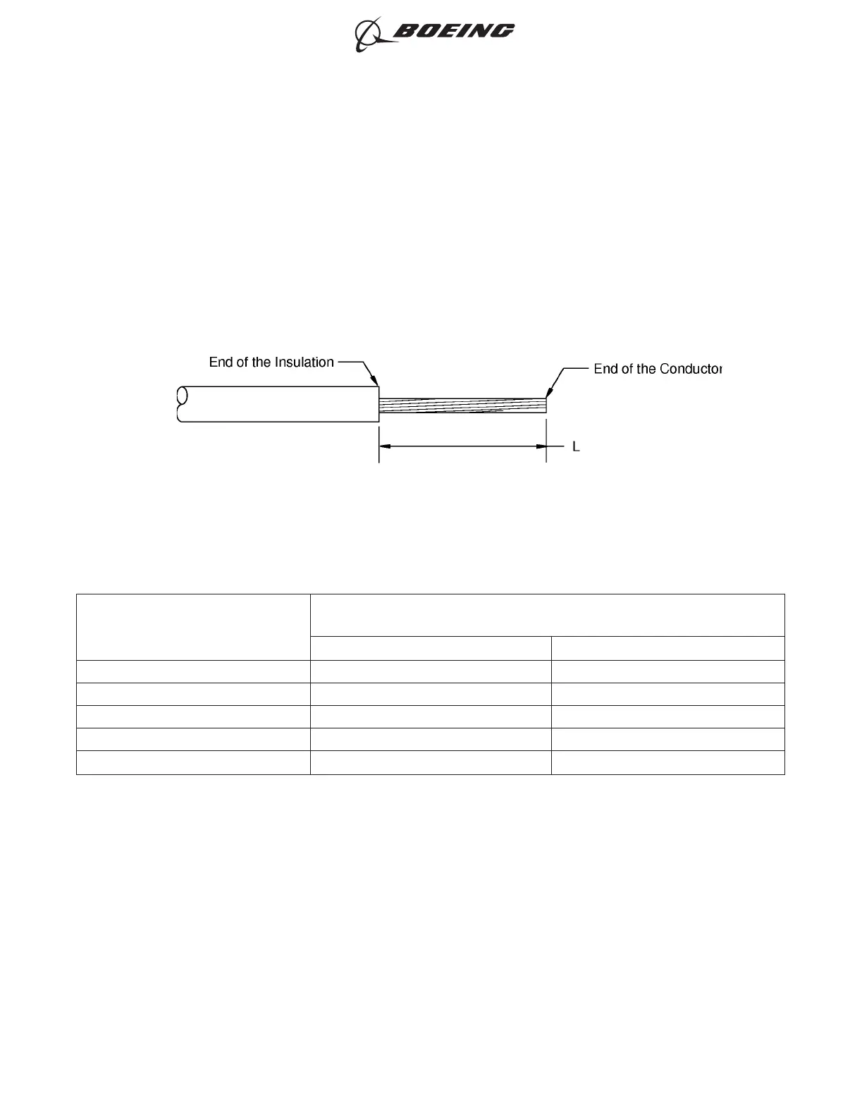
(6) Remove the necessary length of insulation from the end of each wire.
Refer to:
• Figure 12
• Table 61 for the insulation removal length
• Subject 20-00-15 for the insulation removal procedures.
Table 60
INSULATION REMOVAL LENGTH
Splice Part Number
Insulation Removal Length L
(inch)
Target Tolerance
D-609-04 0.28 ±0.03
D-609-05 0.28 ±0.03
D-609-14 0.28 ±0.03
34137 0.34 ±0.03
34138 0.34 ±0.03
(7) Put the splice in the crimp tool.
(8) If the splice has a seam, align the seam opposite the indenter. Refer to Figure 13.
INSULATION REMOVAL LENGTH
Figure 12
ASSEMBLY OF SPLICES
707, 727-787
STANDARD WIRING PRACTICES MANUAL
20-30-12
Page 58
Feb 15/2021D6-54446
ECCN 9E991 BOEING PROPRIETARY - See title page for details