(5) Make a selection of a crimp tool from Table 46.
(6) Make a selection of a Temperature Grade D insulation tape from Table 52.
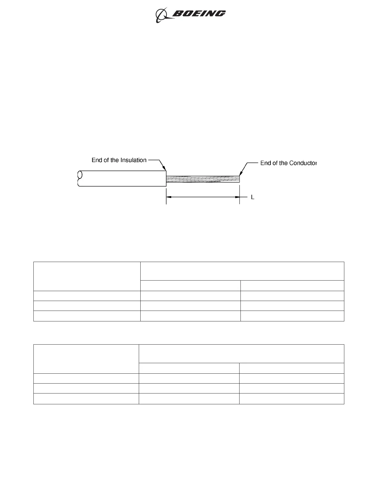
(7) Remove the necessary length of insulation from the end of the wires.
Refer to:
• Figure 134
• Table 95 for the insulation removal length for a wire that can go into the insulation grip
• Table 96 for the insulation removal length for a wire that cannot go into the insulation grip
• Subject 20-00-15 for the insulation removal procedures.
Table 95
INSULATION REMOVAL LENGTH FOR A WIRE THAT CAN GO INTO THE INSULATION GRIP
Splice Part Number
Insulation Removal Length L
(inch)
Target Tolerance
BACT12C11 0.37 ±0.02
BACT12C15 0.23 ±0.02
BACT12C20 0.23 ±0.02
Table 96
INSULATION REMOVAL LENGTH FOR A WIRE THAT CANNOT GO INTO THE INSULATION GRIP
Splice Part Number
Insulation Removal Length L
(inch)
Target Tolerance
BACT12C11 0.46 ±0.02
BACT12C15 0.30 ±0.02
BACT12C20 0.30 ±0.02
(8) Assemble one end of the butt splice.
(a) Put the splice in the crimp tool.
(b) Hold the splice in position with light pressure.
INSULATION REMOVAL LENGTH
Figure 134
ASSEMBLY OF SPLICES
707, 727-787
STANDARD WIRING PRACTICES MANUAL
20-30-12
Page 160
Jun 15/2021D6-54446
ECCN 9E991 BOEING PROPRIETARY - See title page for details