Table 89
INSULATION REMOVAL LENGTH
Splice Part Number
Insulation Removal Length L
(inch)
Target Tolerance
BACT12C11 0.46 ±0.02
BACT12C15 0.30 ±0.02
BACT12C20 0.30 ±0.02
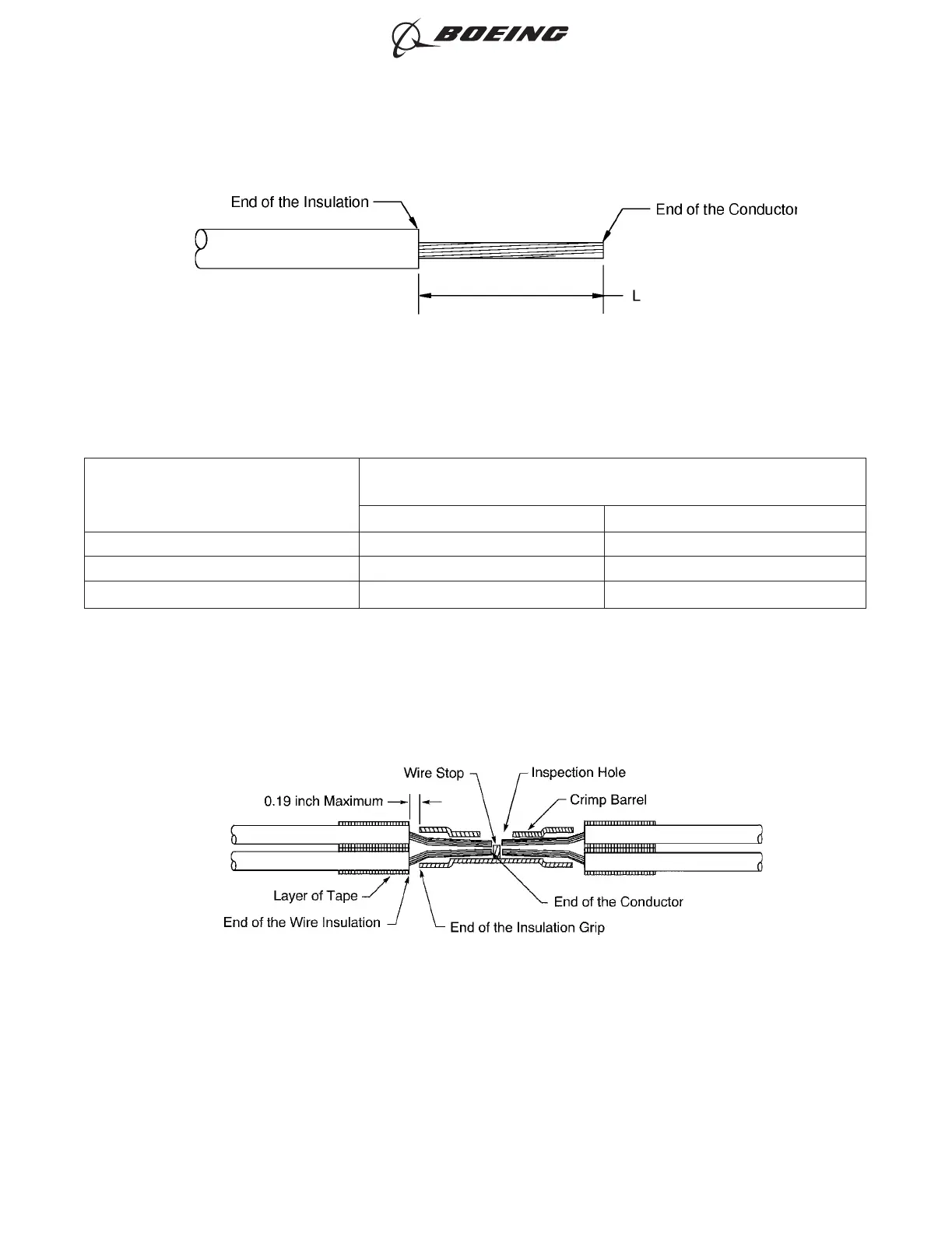
(6) Put the wires in the splice. Refer to Figure 113.
Make sure that:
• The end of each conductor can be seen in the inspection hole
• The end of each conductor does not make an overlap with the wire stop
• The end of each wire insulation is a maximum of 0.19 inch from the end of the insulation
grip.
(7) If it is necessary, remove more insulation from the end of the wire to make the wire fit correctly in
the splice.
(8) Wind a layer of the insulation tape on each wire. Refer to Figure 113.
INSULATION REMOVAL LENGTH
Figure 112
POSITION OF THE WIRES IN THE BUTT SPLICE
Figure 113
ASSEMBLY OF SPLICES
707, 727-787
STANDARD WIRING PRACTICES MANUAL
20-30-12
Page 139
Jun 15/2021D6-54446
ECCN 9E991 BOEING PROPRIETARY - See title page for details