(14) Turn the splice assembly approximately 180 degrees longitudinally.
(15) Put the end of the other wire in the empty crimp barrel of the splice. Refer to Figure 7.
Make sure that:
• If the end of the splice has a blue ring, the wire in that end of the splice is a copper wire
• All of the conductor strands are in the crimp barrel
• The end of the wire insulation is against the insert funnel.
CAUTION
DO NOT TURN THE WIRE DURING OR AFTER THE INSERTION OF THE
WIRE INTO THE SPLICE.
(16) Do again Step 4.H.(8) through Step 4.H.(13) again for the other end of the splice.
(17) Examine the angle of the splice. Refer to Figure 14.
Make sure the angle of the crimped end of the splice to the longitudinal axis is less than 10
degrees.
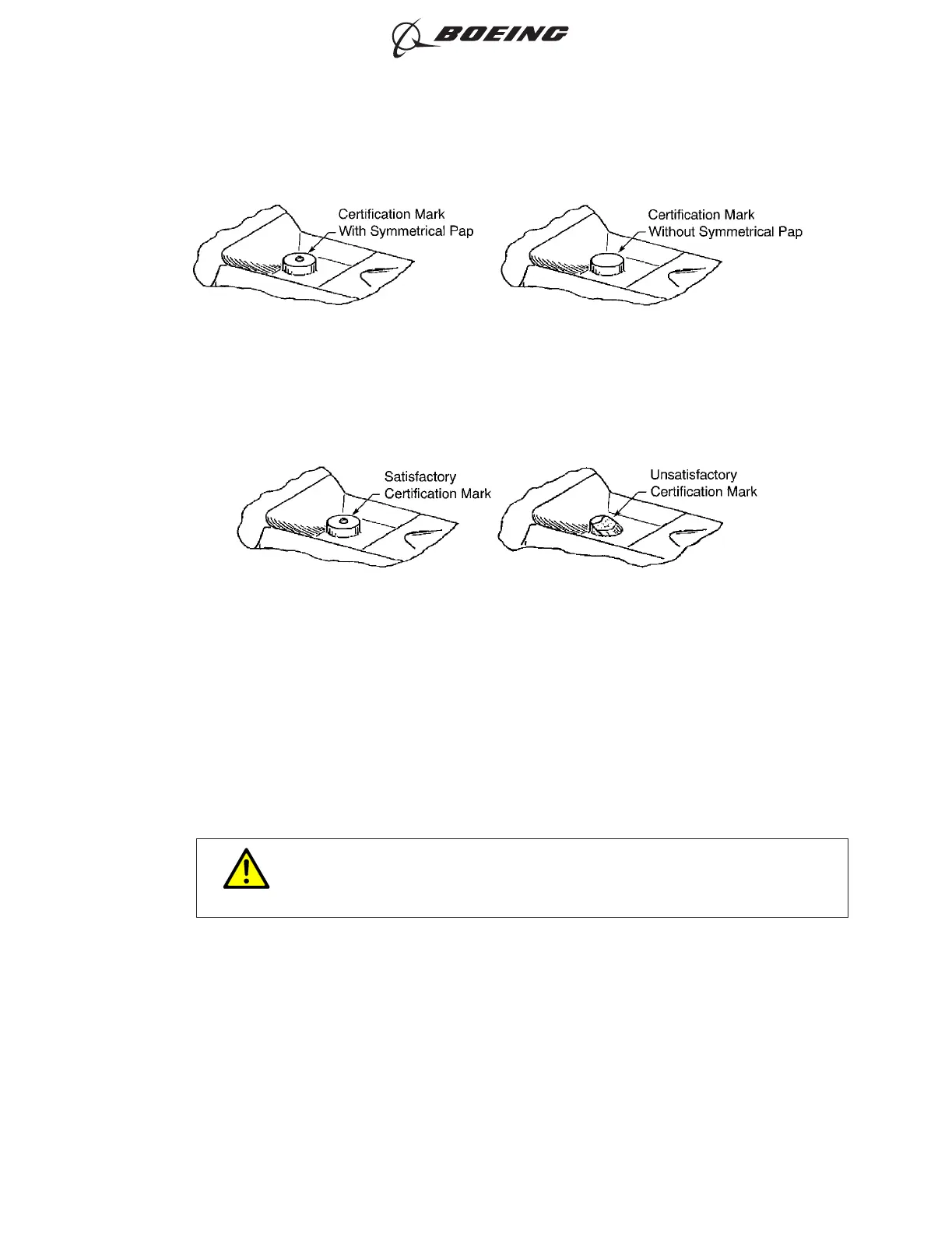
CERTIFICATION MARK
Figure 12
SATISFACTORY AND UNSATISFACTORY CERTIFICATION MARKS
Figure 13
ASSEMBLY AND REPAIR OF THE AMP AND BACS52N COPALUM SPLICES
707, 727-787
STANDARD WIRING PRACTICES MANUAL
20-30-13
Page 26
Oct 15/2017D6-54446
ECCN 9E991 BOEING PROPRIETARY - See title page for details