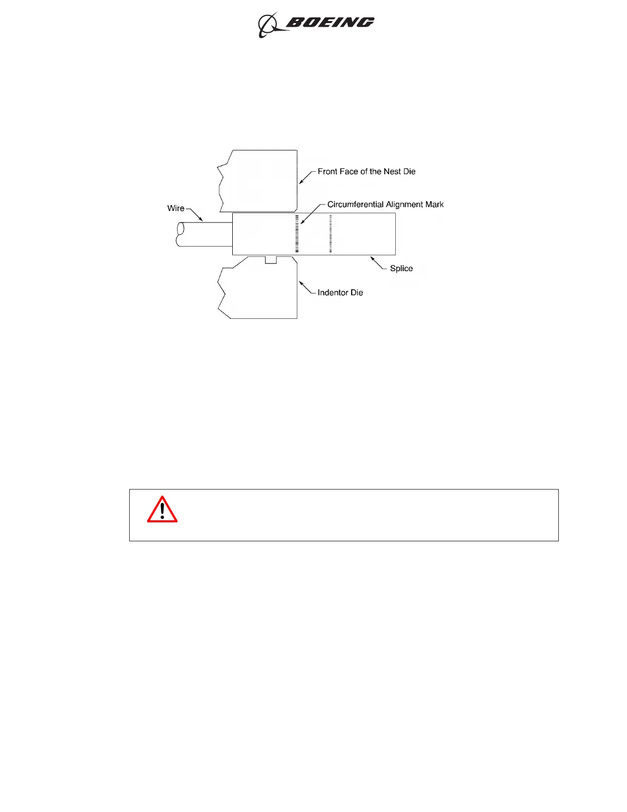
(a) Align the center of the circumferential splice crimp alignment mark with the edge of the nest
die.
(b) Align the longitudinal crimp alignment mark with the alignment dot on the nest die.
(10) Crimp the splice.
Make sure that the alignment of the splice in the die does not change.
WARNING
KEEP HANDS AWAY FROM THE DIES WHEN THE CRIMP TOOL IS
ACTIVATED. INJURY TO PERSONNEL CAN OCCUR.
(11) Remove the splice from the crimp tool.
(12) Remove all the flash and the sharp edges on the splice.
(13) Examine the splice.
Make sure that:
• The edge of the mold line from the die is between the ends of the circumferential alignment
mark on the splice; refer to Figure 11
• The side of the splice with the longitudinal alignment mark is opposite the side of the splice
with the certification mark
• The certification mark can be seen in the bottom and the center of the crimp dent; refer to
Figure 12
• The certification mark is a clearly formed, cylindrical button; refer to Figure 13
POSITION OF THE SPLICE IN THE CRIMP TOOL - SIDE VIEW
Figure 10
ASSEMBLY AND REPAIR OF THE AMP AND BACS52N COPALUM SPLICES
707, 727-787
STANDARD WIRING PRACTICES MANUAL
20-30-13
Page 24
Oct 15/2017D6-54446
ECCN 9E991 BOEING PROPRIETARY - See title page for details