(b) Shrink the sleeve into its position. Refer to Subject 20-10-14.
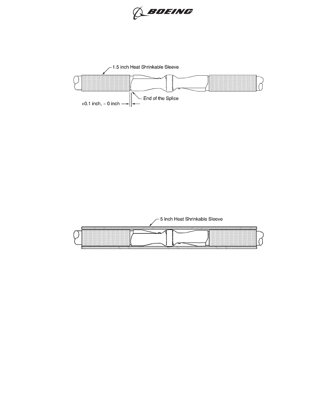
(c) On the other wire, push the 1/4 inch diameter sleeve to the splice until the forward end of
the sleeve is against the end of the splice. Refer to Figure 15.
Make sure that the end of the sleeve is a maximum of 0.1 inch from the end of the splice.
(d) Shrink the sleeve into its position. Refer to Subject 20-10-14.
(e) Align the center of the 1/2 inch diameter sleeve with the center of the splice. Refer to Figure
16.
(f) Shrink the sleeve into its position. Refer to Subject 20-10-14.
(5) If layers of tape will be used for the splice insulation, install the layers of tape.
(a) Make a selection of an insulation tape from Table 7.
(b) Wind three layers of tape on the wire insulation at one end of the splice. Refer to Figure 17.
Make sure that:
• The end of the layer of tape is a maximum of 0.1 inch from the end of the splice
• The layers of tape do not make an overlap with the splice
• The layers of tape have 100 percent overlap.
POSITION OF THE HEAT SHRINKABLE SLEEVE
Figure 15
POSITION OF THE SLEEVES ON THE SPLICE ASSEMBLY
Figure 16
ASSEMBLY AND REPAIR OF THE AMP AND BACS52N COPALUM SPLICES
707, 727-787
STANDARD WIRING PRACTICES MANUAL
20-30-13
Page 28
Oct 15/2015D6-54446
ECCN 9E991 BOEING PROPRIETARY - See title page for details