• Table 43 for BACT12C() splices
• Table 44 for NAS1387-() splices
• Table 45 for BACS52K() splices
• Table 45 for Raychem D-609-0() splices.
(4) Make a selection of a sleeve with 3 to 5 holes in the wire seal from Table 18.
Make sure that the selection is for:
• The applicable splice
• The maximum number of wires in each end of the splice assembly.
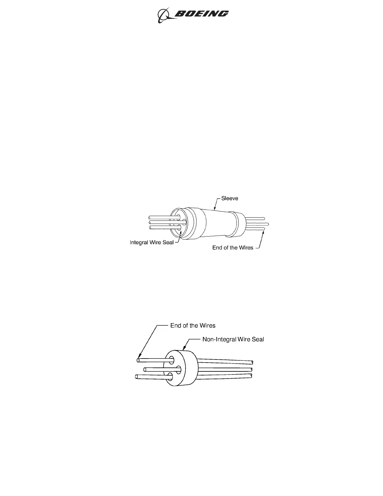
(5) Put the sleeve on all the wires of one end of the splice assembly. Refer to Figure 3 and Figure 80.
Make sure that:
• The end of the sleeve that has the integral wire seal goes on the wires first
• No more than two wires are in one hole of the wire seal.
(6) Put the non-integral wire seal on all the wires of the other end of the splice assembly. Refer to
Figure 3 and Figure 81.
Make sure that no more than two wires are in one hole of the wire seal.
(7) Remove the necessary length of insulation from the end of each wire.
Refer to:
SLEEVE ON THE WIRES
Figure 80
NON-INTEGRAL WIRE SEAL ON THE WIRES
Figure 81
ASSEMBLY OF SPLICES
707, 727-787
STANDARD WIRING PRACTICES MANUAL
20-30-12
Page 109
Feb 15/2021D6-54446
ECCN 9E991 BOEING PROPRIETARY - See title page for details