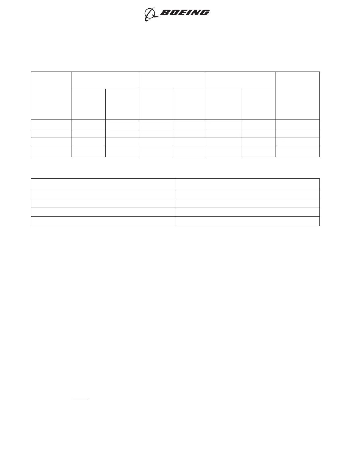
Table 142
DIMENSIONS OF THE SPLICE KITS
Splice Kit Part
Number
One End of Splice
Assembly
Other End of Splice
Assembly
Conductor CAU Range
Conductor
Splice Crimp
Barrel Size
Jacket
Maximum
O.D.
(inch)
Shield
Minimum
O.D.
(inch)
Jacket
Maximum
O.D.
(inch)
Shield
Minimum
O.D.
(inch)
Minimum Maximum
D-150-0250 0.18 0.10 0.18 0.10 8 27 20-16
D-150-0251 0.18 0.10 0.28 0.16 19 67 16-12
D-150-0252 0.28 0.16 0.28 0.16 8 27 20-16
D-150-0253 0.28 0.16 0.35 0.20 19 67 16-12
Table 143
SPLICE ASSEMBLY CONFIGURATION PROCEDURES
Splice Kit Part Number Procedure
D-150-0250 Paragraph 16.B.
D-150-0251 Paragraph 16.C.
D-150-0252 Paragraph 16.D.
D-150-0253 Paragraph 16.E.
(1) Make a selection of the applicable splice kit for the wire or cable configuration from Table 141.
(2) Measure these dimensions of the wire or cable on each side of the splice:
• The jacket O.D.
• The shield O.D.
(3) Compare these dimensions with the applicable dimensions of the splice kit in Table 142:
• The jacket O.D.
• The shield O.D.
(4) If the O.D. of the jackets or the shields are not the correct dimension for the splice kit, make a
selection of an alternative splice configuration. Refer to Paragraph 1.C.
(5) Calculate the total CAU of the conductors for each end of each conductor splice. Refer to
Paragraph 1.D.
(6) Compare the total conductor CAU with the applicable conductor CAU of the splice kit in Table
142.
(7) If the CAU of the conductors are not the correct size for the splice kit, the conductors can be
increased.
Refer to:
• Paragraph 2.B. to assemble the conductor splice with a conductor that is folded back
• Paragraph 2.C. to assemble the conductor splice with a filler wire.
NOTE: As an alternative, make a selection of a different splice configuration. Refer to Paragraph
1.C.
ASSEMBLY OF SPLICES
707, 727-787
STANDARD WIRING PRACTICES MANUAL
20-30-12
Page 336
Jun 15/2021D6-54446
ECCN 9E991 BOEING PROPRIETARY - See title page for details