(1) If one build-up sleeve is specified, put a 1.0 inch ±0.1 inch length of the specified sleeve on the
applicable wiring. Refer to Table 3.
(2) If two build-up sleeves are specified, put the specified sleeves on the applicable wiring. Refer to
Table 3.
(a) Put a 0.9 inch ±0.1 inch length of the larger sleeve on the wiring.
(b) Put a 1.0 inch ±0.1 inch length of the other sleeve on the wiring.
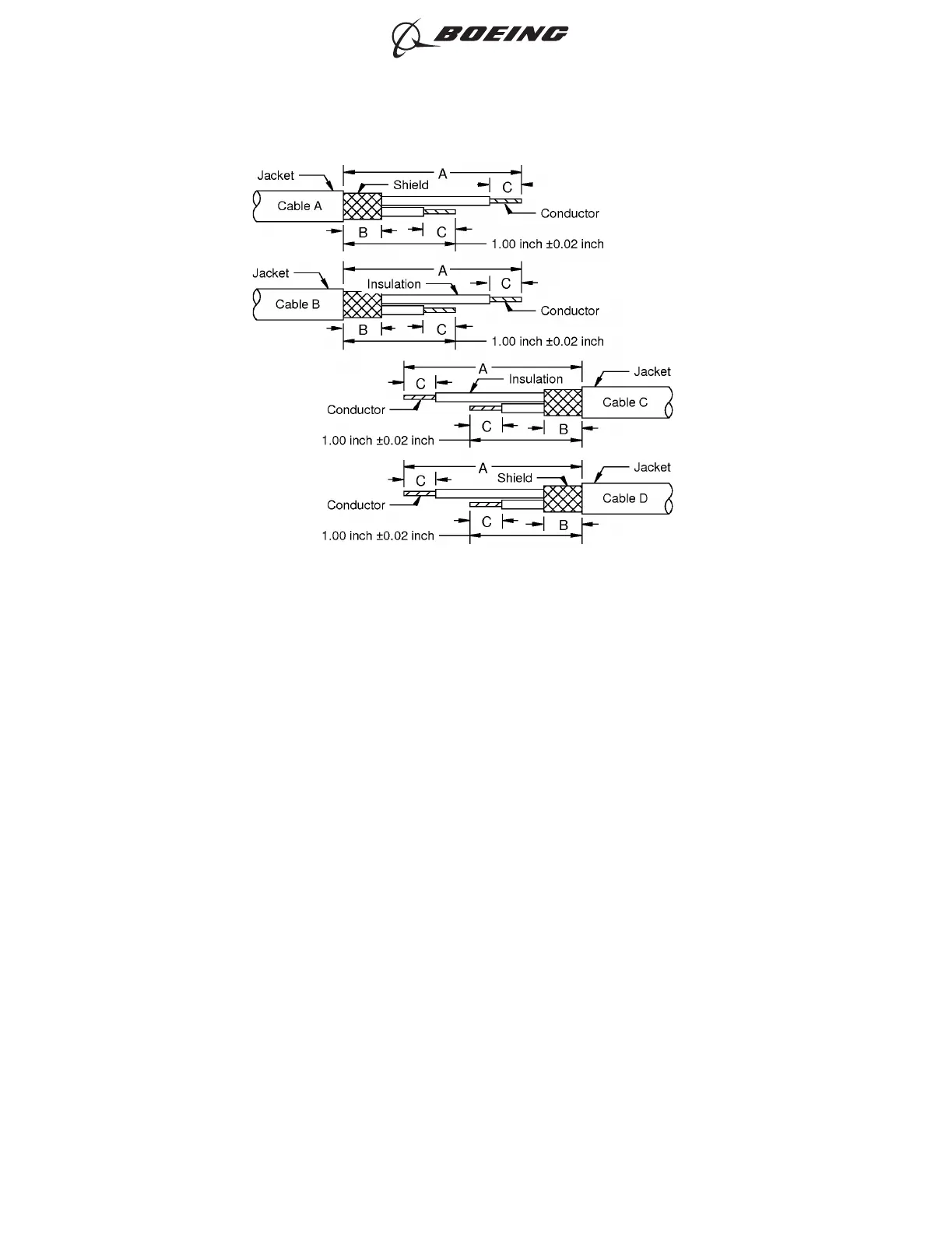
(3) Prepare the end of each cable.
Refer to:
• Table 5 for the configuration of the wiring
• Table 6 for the cable preparation dimensions.
(a) Remove the necessary length of jacket from the cable that makes the distance from the end
of the jacket to the end of the cable equal to dimension A.
Refer to Subject 20-00-15 for the procedure to remove the cable jacket.
(b) Remove the necessary length of shield that makes the distance from the end of the jacket to
the end of the shield equal to dimension B.
(c) For each wire in the cable, remove the necessary length of insulation that makes the
distance from the end of the insulation to the end of the equal to dimension C.
Refer to Subject 20-00-15 for the procedure to remove the insulation.
(4) Put the solder shield sleeve on the cable or cables that are on the end of the splice assembly that
has the smallest number of cables or the cable with the smallest diameter.
CABLE PREPARATION - 2 CABLES TO 2 CABLES, 2 CONDUCTORS
Figure 15
ASSEMBLY OF BACS52R SHIELDED SPLICES
707, 727-787
STANDARD WIRING PRACTICES MANUAL
20-30-19
Page 19
Oct 15/2015D6-54446
ECCN 9E991 BOEING PROPRIETARY - See title page for details