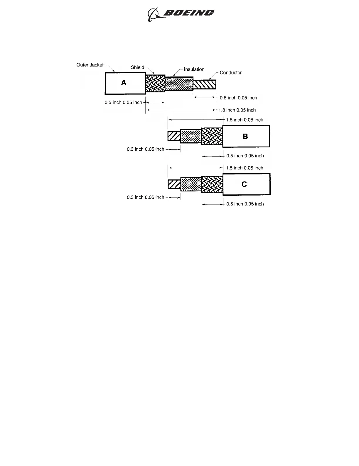
(a) Remove the necessary length of the outer jacket so that the distance from the end of the
outer jacket to the end of the conductor is:
• 1.80 inches ±0.05 inch for Cable A
• 1.50 inches ±0.05 inch for Cable B and Cable C.
(b) Remove the necessary length of the shield so that the distance from the end of the shield to
the end of the outer jacket is 0.50 inch ±0.05 inch for each cable.
(c) Remove the necessary length of the insulation so that the distance from the end of the
insulation to the end of the conductor is:
• 0.60 inch ±0.05 inch for Cable A
• 0.30 inch ±0.05 inch for Cable B and Cable C.
(2) Remove a short length of each end of the shield tube so that the diameter of the tube can be
increased.
(3) In this order, put these components on cable A:
• The outer sleeve
• A seal insert
• The large solder sleeve so that the end of the sleeve with the larger diameter is pointed
toward the end of the wire
• The small solder sleeve so that the end of the sleeve with the larger diameter is pointed
toward the end of the wire
• The shield tube
CABLE PREPARATION
Figure 301
ASSEMBLY OF SPLICES
707, 727-787
STANDARD WIRING PRACTICES MANUAL
20-30-12
Page 341
Jun 15/2021D6-54446
ECCN 9E991 BOEING PROPRIETARY - See title page for details