(2) Twist the end of the shield material until it is tight against the shield of the cable.
(3) For a cable where the shield is not folded back, install a solder sleeve at the end of the shield
material.
Refer to:
• Figure 4
• Subject 20-10-15 for the procedure to install a solder sleeve without an integral wire.
Make sure that:
• The rear edge of the solder ring is approximately 0.1 inch from the end of the cable jacket
• The rear seal ring does not make an overlap with the shield
• The heat is applied at the end of the solder sleeve that is on the shield material first
• The heat applied at the other end of the solder sleeve to melt it around the cable jacket
• The heat applied at the center of the solder sleeve and the cable is turned in the reflector
until the solder melts.
NOTE: A change of the color of the sleeve is permitted if the solder joint can be seen.
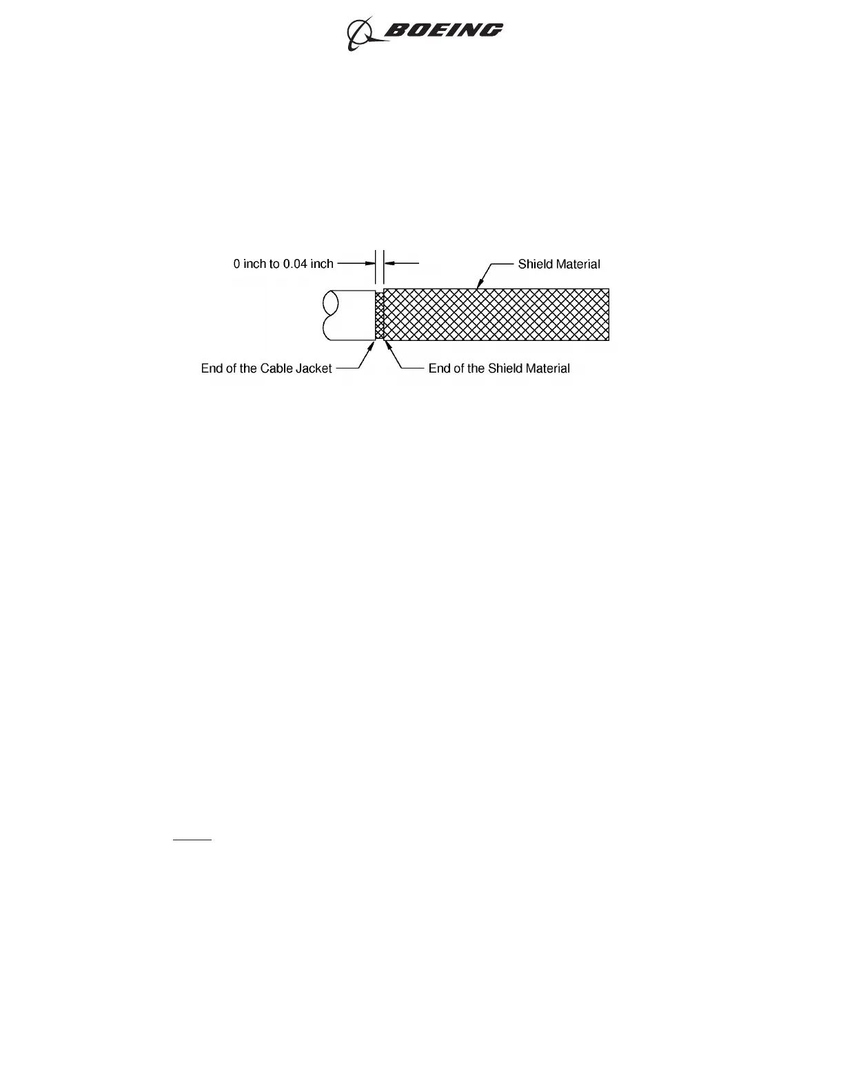
POSITION OF THE SHIELD MATERIAL AT THE END OF THE CABLE JACKET
Figure 3
ASSEMBLY OF BACS52P SERIES AND D-150-0300 SERIES SHIELDED SPLICE ASSEMBLIES
707, 727-787
STANDARD WIRING PRACTICES MANUAL
20-30-20
Page 71
Jun 15/2021D6-54446
ECCN 9E991 BOEING PROPRIETARY - See title page for details