Construction Mode
2-74 Manual # 42-02-7223
Manual Drive Setup Procedure (Quattro DC Drive)
MCE recommends performing the Automated Drive Setup Procedure previously described.
However, if the automated procedure is unsuccessful, the manual procedure may be used. The
1. Verify that Pattern scaling is set to 100% (Configuration > Pattern > Common tab).
2. With zero speed commanded (car idle), observe the D1-Speed Command on the Quattro
Drive operator and verify that the pattern voltage applied to the AC drive unit reads 0.0
volts. If not, adjust Output DAC on the Drive/Calibration screen by entering and send-
ing small negative or positive values until the reading is 0 fpm. The DAC adjustment
range is from —0.25 to +0.25 units.
3. On iView, display the Drive - Offsets (Configuration > Drive > Calibration tab). Also dis-
play the Virtual Oscilloscope (View > Diagnostics > Virtual Oscilloscope) and set Test
point 1 = Tachometer Signal.
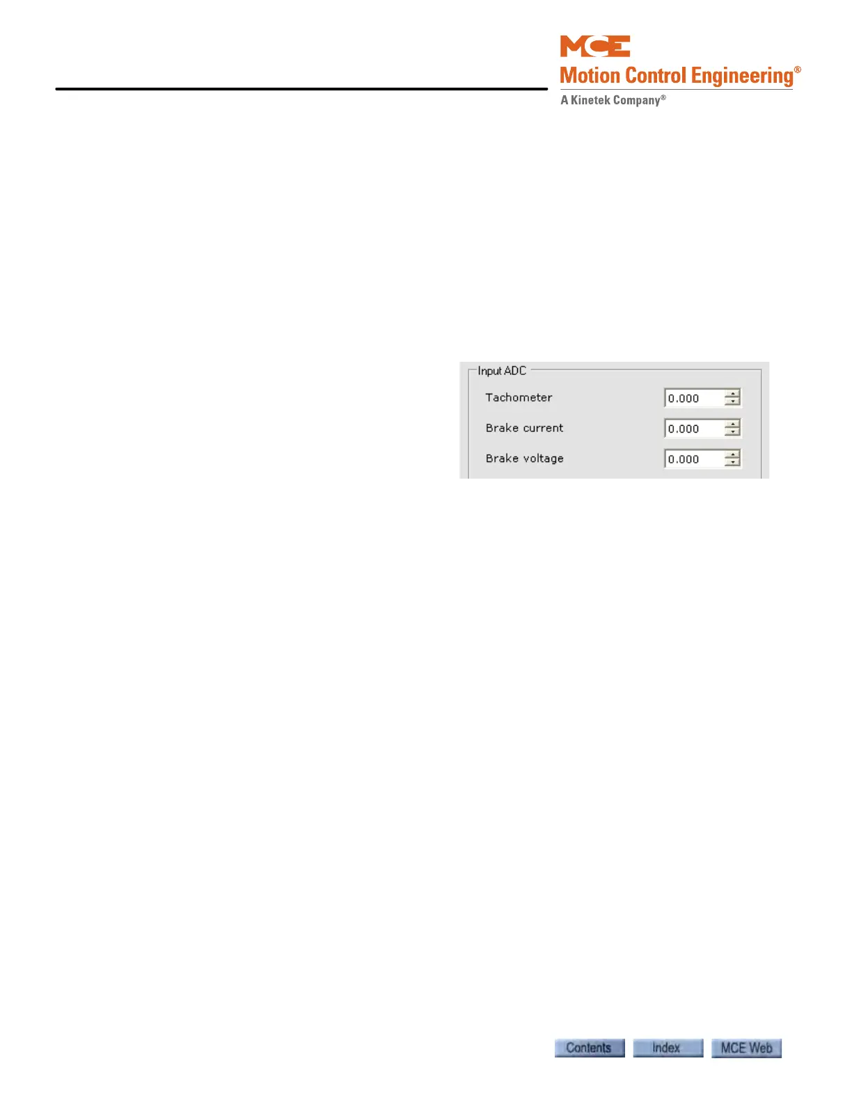
4. Adjust the Input ADC - Tachometer
parameter by entering and sending
small negative or positive values until
the Test point 1 value is as close to 0.0
as possible (A 20mV). The ADC adjust-
ment range is from —0.5 to +0.5.
5. Set the Virtual Oscilloscope Test Point 1 = Brake Current Feedback and then adjust the
Input ADC - Brake current parameter by entering and sending small negative or positive
values until the Test point 1 value is as close to 0.0 as possible.
Set the Virtual Oscilloscope Test Point 1 = Brake Voltage Feedback and then adjust the Input
ADC - Brake voltage parameter by entering and sending small negative or positive values until
the Test point 1 value is as close to 0.0 as possible.
Auto Tune Procedure (Quattro DC Drive)
The Auto Tune Procedure is described in the Appendix of the Magnetek Quattro DC Drive man-
ual. The procedure allows the drive to calculate the following motor parameters:
- Armature Inductance - Armature Resistance
- Field Resistance - Field Time Constant
- Armature Resistance Voltage Drop at Motor Rated Current
1. Temporarily jumper terminals TB1 to F2 and TB4 to F1 (located in the Quattro Drive
Cabinet on the top). These terminals should also be available on the terminal block at
the bottom of the Controller cabinet (please see prints). This will bypass the PM1 con-
tacts and allow the Quattro DC Drive to pick its ME contactor (motor contactor).
2. Care must be taken not to short the secondary of the transformer that is the source of
power for these terminals.
3. On the A4 MS Pwr Convert Menu, auto-tune the motor with the Auto Tune Motor
parameter. With the parameter selected, press the Enter key twice to begin the process
(please see Auto Tune Procedure in the Appendix of the Quattro Technical Manual).
4. After the auto-tune process is completed, transfer the tuned parameters from the A6
menu to the A4 menu.
5. Remove the temporary jumpers from terminals TB1/F2 and TB4/F1.