Drive Startup (System 12 SCR Drive)
2-47
2
iControl DC
Drive Startup (System 12 SCR Drive)
The following startup instructions pertain to the System 12 SCR Drive. For startup instructions
for the Magnetek Quattro DC drive see “Drive Startup (Quattro DC Drive)” on page 2-71.
Check SCR Drive Voltage and Polarity
1. Ensure power is OFF at the main disconnect.
2. Set the iBox Inspection switch to the Inspection position.
3. Set the iBox Controller Stop switch to the Stop position.
4. Set the iBox Test switch to On.
5. Disable the hoist motor by lifting all sets of motor brushes and putting cardboard under
them (or tie them back so that no contact is made).
6. Remove the brake wire from terminal B1 to prevent the brake from picking.
7. Turn on power at the main disconnect.
8. Watch the front panel displays of the iBox, the controller will take about 60 seconds to
initialize.
9. Check the iBox Computer, Safety A, and Safety B status LEDs. The LEDs should be
lighted solid green.
10. Check the 3-phase AC voltages at X1, X2, X3, and Y1, Y2, Y3 on the contactors at the bot-
tom of the SCR drive. They should match the voltage for the secondary windings of the
Drive Isolation Transformer as shown on page -D1 of the job prints.
11. Verify that the fan(s) in the resistor cabinet are functional.
12. Look for the Drive Ready indicator on the SCR drive. It should light within 5 seconds
after the iBox initializes. If the DRIVE READY LED did not light, leave the motor dis-
abled and the brake B1 lead disconnected, go to “If DRIVE READY Did Not Light” and
follow the conditional steps below.
13. If the Drive Ready indicator did
light, restore hoist motor brush
contact. Reconnect the brake ter-
minal B1 wire. Please refer to
“Motor Field Calibration (System
12 SCR Drive)” on page 2-53.
If DRIVE READY Did Not Light:
14. Measure between 1 and 2D on the
System 12 drive (should read
120VAC).
15. Check fuse F2D. Replace the fuse
if necessary. If the Drive Ready
LED does not light, make a note of
any lighted LEDs on the SCR
Drive, and turn power off at the
main disconnect.
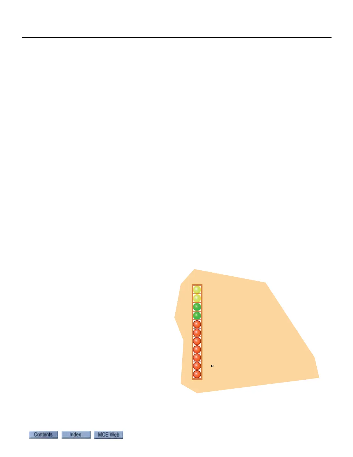
UP DIRECTION
DOWN DIRECTION
DRIVE READY
DRIVE ON
CURRENT LIMIT
LOW LINE - WYE SECONDARY
LOW LINE - DELTA SECONDARY
WYE P.R.
DELTA P.R.
30 P.R.
CONTACTOR OR HIGH CURRENT FUSE FAILURE